Isuzu Amigo / Axiom / Trooper / Rodeo / VehiCross. Manual - part 185


  Index      Isuzu     Isuzu Amigo / Axiom / Trooper / Rodeo / VehiCross - service repair manual 1999-2002 year


Search            


Content   ..  183  184  185  186   ..


Isuzu Amigo / Axiom / Trooper / Rodeo / VehiCross. Manual - part 185


5C–57

POWER–ASSISTED BRAKE SYSTEM

Machining The Drum

If a drum is to be machined, only enough metal should be
removed to obtain a true, smooth braking surface.  If a
drum does not clean-up when machined to a maximum
diameter, it must be replaced.  Removal of more metal will

affect dissipation of heat and may cause distortion of the
drum.
After refinishing, replace any drum that exceeds a
maximum inside diameter of 296.5 mm (11.673 in).  Do
not use a brake drum that is not within the specification.

Maximum inside diameter: 296.5 mm (11.673 in)

Wheel Cylinder Assembly (4

×

2 Model)

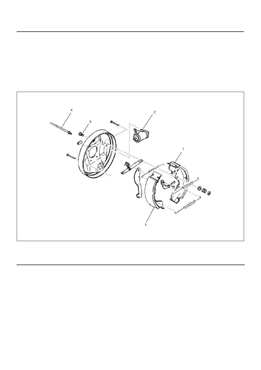
Wheel Cylinder Assembly and Associated Parts

305RW003

Legend

(1) Brake Linings
(2) Wheel Cylinder

(3) Bolts
(4) Brake Pipe

Removal

1. Remove brake linings (1).

D

Refer to 

Brake Lining and Associated Parts in this

section.

2. Remove brake pipe (4).

D

Plug the opening in the line to prevent fluid loss and
contamination.

3. Remove bolts (3) and wheel cylinder (2).

Installation

1. Install wheel cylinder (2) and tighten bolts (3) to the

specified torque.

Torque: 10 N·m (8 lb ft)

2. Install brake pipe (4) and tighten the nut to the

specified torque.

Torque: 16 N·m (12 lb ft)

3. Install brake linings (1).

D

Refer to 

Brake Lining Replacement in this section.

D

Bleed brake system.  Refer to 

Hydraulic Brake in

this section.

5C–58 POWER–ASSISTED BRAKE SYSTEM

Disassembled View

305RS006

Legend

(1) Boot
(2) Piston Assembly
(3) Piston Cup
(4) Return Spring
(5) Bleeder
(6) Wheel Cylinder

Disassembly

1. Remove boot (1) and piston assembly (2).
2. Remove piston cup (3) from piston assembly (2).
3. Remove return spring (4) and bleeder (5) from wheel

cylinder (6).

Inspection and Repair

1. Make necessary parts replacement if wear, damage,

corrosion or any other abnormal condition are found
through inspection.
Check the following parts;

D

Wheel cylinder body

D

Cylinder bore

D

Piston

D

Return spring

D

Bleeder

NOTE: Replace the piston cups and boots each time the
wheel cylinder is overhauled.  Discard these used rubber
parts and replace with new ones.

Reassembly

1. Lubricate the cylinder bore with clean rubber grease.

305RS007

2. Install bleeder (5) to wheel cylinder (6).

Torque: 10 N·m (8 lb ft)

305RS008

5C–59

POWER–ASSISTED BRAKE SYSTEM

3. Install new piston cups (3) on each piston so that the

flared end of the cups are turned to the inboard side of
the pistons.
Attach the return spring (4) and the boot (1) to the
piston.

305RS009

4. Apply DELCO silicone lube No. 5459912 (or

equivalent) to the piston and the inner face of the
boots.

5. Install piston assembly (2) to wheel cylinder (6).

5C–60 POWER–ASSISTED BRAKE SYSTEM

Main Data and Specifications

General Specifications

Rear drum brake

Type

Leading-trailing, non-servo

Drum inside diameter

295 mm (11.6 in)

Wheel cylinder diameter

22.22 mm (7/8 in)

Torque Specifications

E05RW010


Content   ..  183  184  185  186   ..