Content .. 1728 1729 1730 1731 ..
Isuzu Amigo / Axiom / Trooper / Rodeo / VehiCross. Manual - part 1730
FRONT SUSPENSION
3C–21
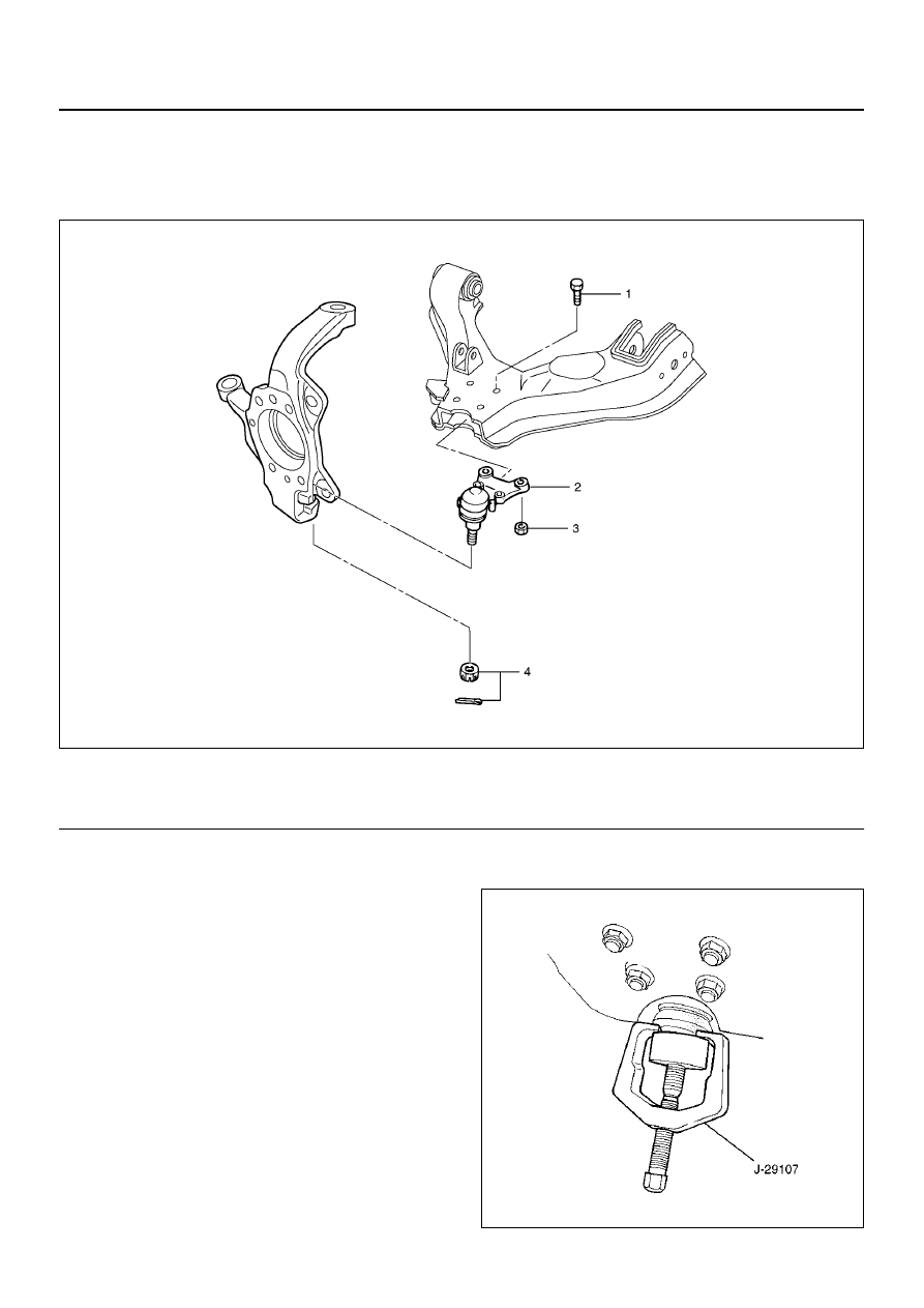
Lower Ball Joint
Lower Ball Joint and Associated Parts
450R200008
EndOFCallout
Removal
1. Raise the vehicle and support the frame with
suitable safety stands.
2. Remove wheel and tire assembly. Refer to Wheel in
this section.
3. Remove the tie-rod end from the knuckle. Refer to
Power Steering Unit in Steering section.
4. Remove the retaining ring from the front axle driving
shaft to release the shaft from hub(Except 2WD
model). Refer to Front Hub and Disc in Driveline/
Axle section.
5. Support lower control arm with a jack.
6. Remove lower ball joint nut and cotter pin, then use
remover J–29107 to remove the lower ball joint from
the knuckle.
CAUTION: Be careful not to damage the ball joint
boot.
901RW163
Legend
(1) Bolt
(2) Lower Ball Joint
(3) Nut
(4) Nut and Cotter Pin