Content .. 1719 1720 1721 1722 ..
Isuzu Amigo / Axiom / Trooper / Rodeo / VehiCross. Manual - part 1721
POWER-ASSISTED STEERING SYSTEM
2A–33
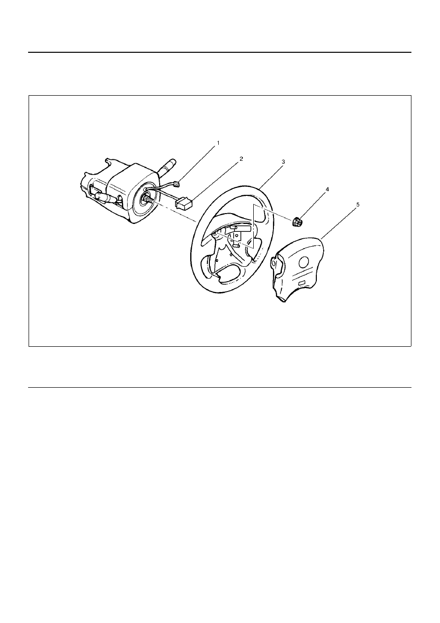
Steering Wheel
Steering Wheel and Associated Parts
827RW069
E nd O FCallo ut
CAUTION: Once the steering column is removed
from the vehicle, the column is extremely
susceptible to damage. Dropping the column
assembly on its end could collapse the steering
shaft or loosen the slide block which maintains
column rigidity. Leaning on the column assembly
could cause the jacket to bend or deform. Any of the
above damage could impair the column's
collapsible design. If it is necessary to remove the
steering wheel, use only the specified steering
wheel puller. Under no conditions should the end of
the shaft be hammered upon, as hammering could
loosen the slide block which maintains column
rigidity.
Removal
1. Turn the steering wheel so that the vehicle's wheels
are pointing straight ahead.
2. Turn the ignition switch to “LOCK".
3. Disconnect the battery ground cable, and wait at
least 5 minutes.
4. Disconnect the yellow 2-way SRS connector located
under the steering column.
Legend
(1)
Horn Lead
(2)
SRS Connector
(3)
Steering Wheel
(4)
Steering Wheel Fixing Nut
(5)
Inflator Module