Content .. 1698 1699 1700 1701 ..
Isuzu Amigo / Axiom / Trooper / Rodeo / VehiCross. Manual - part 1700
9J1–11
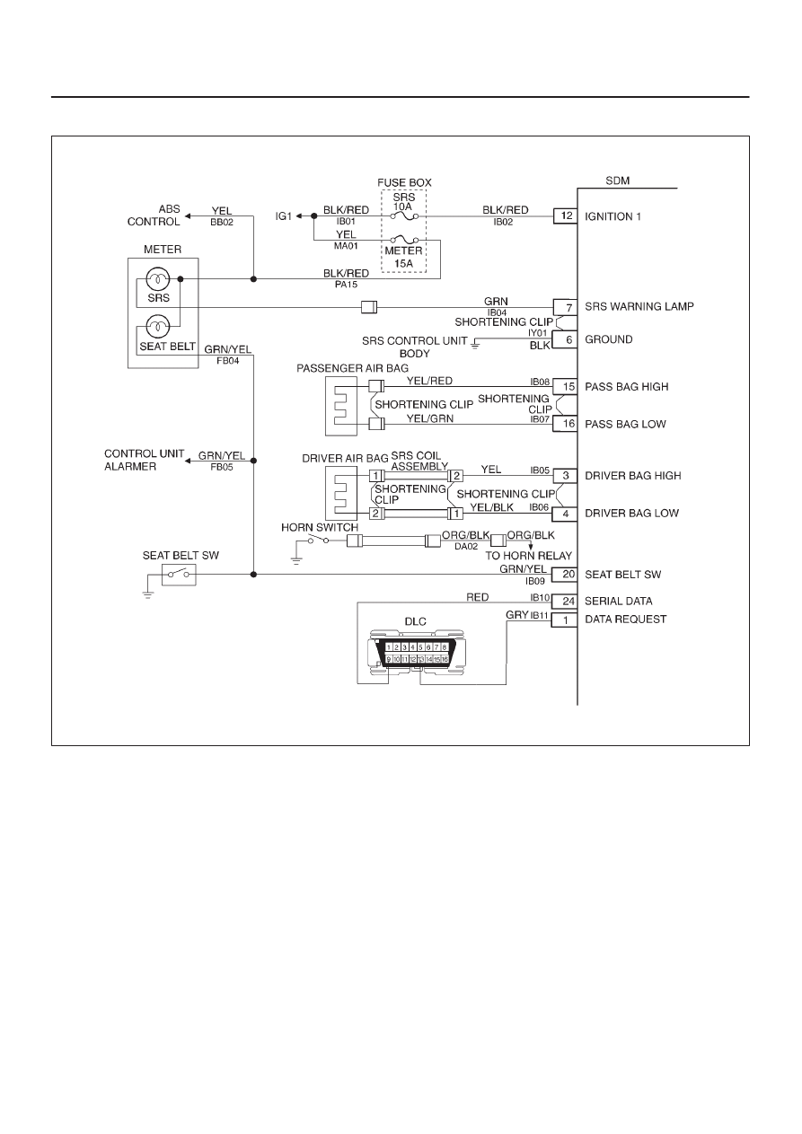
RESTRAINT CONTROL SYSTEM
System Schematic
D09R100002
SRS Diagnostic System Check
The diagnostic procedures used in this section are
designed to find and repair Supplemental Restraint
System (SRS) malfunctions. To get the best results, it is
important to use the diagnostic charts and follow the
sequence listed below:
A. Perform the “SRS Diagnostic System Check.”
The “SRS Diagnostic System Check” must be the
starting point of any SRS diagnostics. The “SRS
Diagnostic System Check” checks for proper “AIR
BAG” warning lamp operation, the ability of the
Sensing and Diagnostic Module (SDM) to
communicate through the “Serial Data” line and
whether SRS diagnostic trouble codes exist.
B. Refer to the proper diagnostic chart as directed by the
“SRS Diagnostic System Check.”
The “SRS Diagnostic System Check” will lead you to
the correct chart to diagnose any SRS malfunctions.
Bypassing these procedures may result in extended
diagnostic time, incorrect diagnosis and incorrect
parts replacement.
C. Repeat the “SRS Diagnostic System Check” after any
repair or diagnostic procedures have been
performed.
Performing the “SRS Diagnostic System Check” after
all repair or diagnostic procedures will ensure that the
repair has been made correctly and that no other
malfunctions exist
Circuit Description
When the ignition switch is first turned “ON”, “ignition 1”
voltage is applied from the “SRS” fuse to the SDM at the
“ignition 1” input terminals “12”. The SDM responds by
flashing the “AIR BAG” warning lamp seven times while
performing tests on the SRS.