Isuzu Amigo / Axiom / Trooper / Rodeo / VehiCross. Manual - part 1695


  Index      Isuzu     Isuzu Amigo / Axiom / Trooper / Rodeo / VehiCross - service repair manual 1999-2002 year


Search            


Content   ..  1693  1694  1695  1696   ..


Isuzu Amigo / Axiom / Trooper / Rodeo / VehiCross. Manual - part 1695


SUPPLEMENTAL RESTRAINT SYSTEM

9J–37

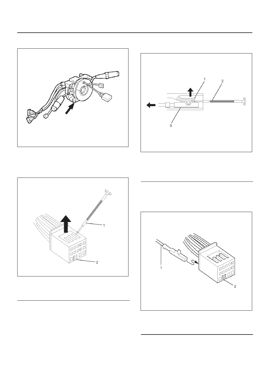
15. Remove four bolts of SRS coil assembly and remove

the SRS coil assembly from the combination switch.

825RX033

How to Disconnect the horn terminal

1. Lift the white part of black connector with a screw

driver (–) and release connector terminal lock.

827R100002

Legend

(1) Screw driver (–)
(2) Connector lock knob

2. Pull out the terminal of lead wire coming to black

connector NO.12 while lifting the lock part with a
screw driver (–).

827100003

Legend

(1) Lock
(2) Screw driver (–)
(3) Terminal

How to Connect  Horn Terminal

1. Insert horn terminal from behind black connector

NO.12 until connector lock works.

827RX047

Legend

(1) Terminal
(2) Connector lock knob

SUPPLEMENTAL RESTRAINT SYSTEM

9J–38

2. Push white connector into the black connector for a

double lock.

827RX048

Installation

1. Set cancel cam and SRS coil in position and install the

SRS coil to combination switch by tightening the four
bolts to a specified tightening torque with four bolts.

Torque: 0.5 N·m (0.05 kg·m/0.4 lb ft)

825RX033

2. Insert the horn terminal into the connector NO.12 and

bind the combination switch harness and SRS coil
harness with a tape.(Refer to How to Connect the
horn terminal in this section.)

3. Install the combination switch assembly (with SRS

coil) to steering lock of steering shaft and tighten the
four bolts to a specified tightening torque.

825RX047

Legend

(1) Horn Lead Connector
(2) Air Bag Harness Connector
(3) Steering Column Cover
(4) Setting Mark
(5) Steering Fixing Nut
(6) Driver Air Bag Assembly
(7) Steering Wheel
(8) Driver Air Bag Fixing Bolts
(9) Combination Switch Assembly

(10) Wiring Harness Connectors

4. Connect the wiring harness connectors (10) located

at the base of steering column.

5. Turn the SRS coil clockwise to full, return about 3

turns and align the neutral mark.

SUPPLEMENTAL RESTRAINT SYSTEM

9J–39

NOTE: Whenever installing the new combination switch
with SRS coil, be sure to tear off the lock pin for aligning
the neutral position before it is installed to the base of
steering column.

825RX032

CAUTION: Turn the SRS coil clockwise until a
resistance is felt, do not over turn or SRS coil
breakage may occur.

6. Install the steering column cover (3).

CAUTION: When installing the steering column
cover, be sure that all harnesses (i.e., starter switch,
combination switch, and SRS coil) are not pinched
and installed according to the diagram below.

825RS048

7. Install the driver knee bloster assembly.
8. Install the steering lower cover.
9. Install the steering wheel and align the setting marks

(4).

10. Tighten the steering wheel fixing nut (5) to the

specified torque.

Torque: 34 N·m (3.5 kg·m/25 lb ft)

11. Connect horn lead (1).

12. Connect air bag to wiring harness connector (2).

NOTE: Pass the lead wire through the tabs on the plastic
cover (wire protector) of air bag to prevent lead wire from
being pinched.

13. Install Air Bag (6) into steering wheel and tighten bolts

(8) to specified sequence as figure.

Torque: 8.8 N·m (0.9 kg·m/78 lb in)

CAUTION: Never use the air bag assembly from
another vehicle. Use only the air bag assembly for
Rodeo Models Only.

825RX047

Legend

(1) Horn Lead Connector
(2) Air Bag Harness Connector
(3) Steering Column Cover
(4) Setting Mark
(5) Steering Fixing Nut
(6) Driver Air Bag Assembly
(7) Steering Wheel
(8) Driver Air Bag Fixing Bolts
(9) Combination Switch Assembly

(10) Wiring Harness Connectors

14. Enable the SRS. (Refer to “Enabling The SRS” in this

section.)

SUPPLEMENTAL RESTRAINT SYSTEM

9J–40

Steering Column

Service Precaution

WARNING: SAFETY PRECAUTIONS MUST BE
FOLLOWED WHEN HANDLING A DEPLOYED AIR
BAG ASSEMBLY. AFTER DEPLOYMENT, THE AIR
BAG ASSEMBLY SURFACE MAY CONTAIN A SMALL
AMOUNT OF SODIUM HYDROXIDE, A BY–PRODUCT
OF THE DEPLOYMENT REACTION, THAT IS
IRRITATING TO THE SKIN AND EYES. MOST OF THE
POWDER ON THE AIR BAG ASSEMBLY IS
HARMLESS. AS A PRECAUTION, WEAR GLOVES
AND SAFETY GLASSES WHEN HANDLING A
DEPLOYED AIR BAG ASSEMBLY, AND WASH YOUR
HANDS WITH MILD SOAP AND WATER
AFTERWARDS.

WARNING: WHEN CARRYING A LIVE AIR BAG
ASSEMBLY, MAKE SURE THE BAG AND TRIM
COVER ARE POINTED AWAY FROM YOU. NEVER
CARRY AIR BAG ASSEMBLY BY THE WIRES OR
CONNECTOR ON THE UNDERSIDE OF MODULE. IN
THE CASE OF AN ACCIDENTAL DEPLOYMENT, THE
BAG WILL THEN DEPLOY WITH MINIMAL CHANCE
OF INJURY. WHEN PLACING A LIVE AIR BAG
ASSEMBLY ON A BENCH OR OTHER SURFACE,
ALWAYS FACE BAG AND TRIM COVER UP, AWAY
FROM THE SURFACE. NEVER REST A STEERING
COLUMN ASSEMBLY ON THE STEERING WHEEL
WITH THE AIR BAG ASSEMBLY FACE DOWN AND
COLUMN VERTICAL. THIS IS NECESSARY SO THAT
A FREE SPACE IS PROVIDED TO ALLOW THE AIR
BAG ASSEMBLY TO EXPAND IN THE UNLIKELY
EVENT OF ACCIDENTAL DEPLOYMENT.
OTHERWISE, PERSONAL INJURY COULD RESULT.

NOTE: In the event deployment has occurred, inspect
coil assembly wire for any signs of scorching, melting or
any other damage due to excessive heat. If the coil has
been damaged, replace it.

Removal

1. Disable the Supplemental Restraint System (SRS).

(Refer to “Disabling The SRS” in this section.)

431RX012

Legend

(1) Steering Column Cover
(2) Steering Wheel
(3) Steering Fixing Nut
(4) Driver Air Bag Assembly
(5) Driver Air Bag Fixing Bolts
(6) Setting Mark
(7) Air Bag Harness Connector
(8) Horn Lead Connector
(9) Combination Switch Assembly

(10) Wiring Harness Connectors

(11) Steering Lock Cylinder Assembly

(12) Starter Switch Harness Connector
(13) Steering Column Assembly
(14) 2nd Column Shaft
(15) Column Shaft Fixing Bolt


Content   ..  1693  1694  1695  1696   ..