Content .. 1647 1648 1649 1650 ..
Isuzu Amigo / Axiom / Trooper / Rodeo / VehiCross. Manual - part 1649
8F–38
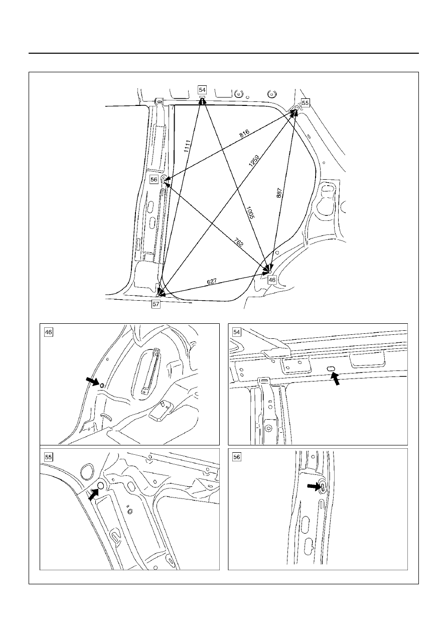
BODY STRUCTURE
Side Body Section (Rear side)
A10RW047
Index Isuzu Isuzu Amigo / Axiom / Trooper / Rodeo / VehiCross - service repair manual 1999-2002 year
|
|
|
Content .. 1647 1648 1649 1650 ..
8F–38 BODY STRUCTURE Side Body Section (Rear side) A10RW047 |