Isuzu Amigo / Axiom / Trooper / Rodeo / VehiCross. Manual - part 1601


  Index      Isuzu     Isuzu Amigo / Axiom / Trooper / Rodeo / VehiCross - service repair manual 1999-2002 year


Search            


Content   ..  1599  1600  1601  1602   ..


Isuzu Amigo / Axiom / Trooper / Rodeo / VehiCross. Manual - part 1601


7B–40

MANUAL TRANSMISSION

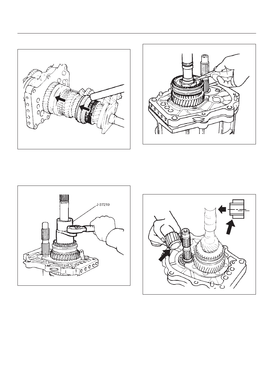
7. Mesh the 1st–2nd and 3rd–4th synchronizers with

both the 1st and 3rd gears (double engagement).

226RS015

This will prevent the mainshaft from turning.

8. Install the new mainshaft hub nut.

Use the mainshaft nut wrench J–37219 to tighten the
mainshaft nut(23) to the specified torque.

Torque: 137 N·m (101 lb ft)

226RS016

9. Use a punch to stake the mainshaft nut.

226RW153

10. Install needle bearing(22), 5th block ring(21), and 5th

gear(20).

11. Apply engine oil to the counter reverse gear(19) and

the reverse gear(26).
Install the counter reverse gear(19) to the counter
shaft.
The reverse gear projection must be facing the
intermediate plate.

226RW151

MANUAL TRANSMISSION

7B–41

12. Install the counter 5th gear(18) to the transmission.

226RS019

13. Install ball bearing(17) and bearing snap ring by

performing the following steps:

D

Select the snap ring which will provide the minimum
clearance between the ball bearing and the snap
ring.

226RS020

D

There are six snap ring sizes available.
The snap rings are color-coded to indicate their
thickness.

226RS021

Ball Bearing and Snap Ring Clearance

Standard: 0–0.15 mm (0–0.0059 in)

Snap Ring Availability

Thickness

Color Coding

1.1 mm (0.043 in)

White

1.2 mm (0.047 in)

Yellow

1.3 mm (0.051 in)

Blue

1.4 mm (0.055 in)

Pink

1.5 mm (0.059 in)

Green

1.6 mm (0.063 in)

Brown

D

Use a pair of snap ring pliers to install the snap
ring(16) to the counter gear shaft.
The snap ring must be fully inserted into the counter
gear shaft snap ring groove.

14. Assemble reverse idler shaft(15), reverse idler

gear(14), thrust washer(13), and idle shaft pin(12)
into reverse idler gear assembly(11).

7B–42

MANUAL TRANSMISSION

15. Select reverse idler gear snap ring(10) which will

provide the minimum clearance between the
intermediate plate(30) and the snap ring(10).

226RS022

D

There are three snap ring sizes available.
The snap rings are color-coded to indicate their
thickness.

Intermediate Plate and Snap Ring Clearance

Standard: 0 – 0.15 mm (0 – 0.0059 in)

Snap Ring Availability

Thickness

Color Coding

1.2 mm (0.047 in)

White

1.3 mm (0.051 in)

Yellow

1.4 mm (0.055 in)

Blue

226RS021

D

Use a pair of snap ring pliers to install the snap ring
to the reverse idler shaft.
The snap ring must be fully inserted into the reverse
idler shaft snap ring groove.

16. Install thrust washer and lock ball(9) by performing

the following steps:

D

Use a thickness gauge to measure the clearance
between the 5th gear and the thrust washer.

5th Gear and Thrust Washer Clearance

Standard: 0.10 – 0.25 mm (0.004 – 0.010 in)

D

Measure clearance “A” as shown in the figure.

226RS023

D

Select appropriate thrust washer from chart.

D

There are four thrust washer sizes available.

D

The thrust washers are color coded to indicate their
thickness.

MANUAL TRANSMISSION

7B–43

Thrust Washer Availability

Thickness

mm (in)

Color

Coding

A mm (in)

Clearance

mm (in)

7.9 (0.311)

White

8.05–8.1

(0.317–0.319)

0.15–0.25

(0.006–0.010)

8.0 (0.315)

Yellow

8.1–8.2

(0.319–0.323)

0.1–0.25

(0.004–0.010)

8.1 (0.319)

Green

8.2–8.3

(0.323–0.327)

0.1–0.25

(0.004–0.010)

8.2 (0.323)

Blue

8.3–8.36

(0.327–0.329)

0.1–0.21

(0.004–0.008)

226RS024

D

Apply grease to the thrust washer and the lock ball.

D

Install the thrust washer and the lock ball.

17. Install thrust plate(8) and retainer(7).
18. Install retaining snap ring(6), clip(5), speedometer

drive gear(4), and bearing snap ring(3). (4X2)

19. Use the installer J–37223 to install the ball bearing(2)

to the mainshaft. (4X2)

226RS096

20. Install bearing snap ring(1). (4X2)
21. Apply engine oil to the bearing inner and outer

circumference. (4X4)
Use the installer J–37223 to install the ball bearing(2)
to the mainshaft in proper direction. (4X4)

226RS025

22. Install oil seal collar(1). (4X4)


Content   ..  1599  1600  1601  1602   ..