Isuzu Amigo / Axiom / Trooper / Rodeo / VehiCross. Manual - part 159
5A–14
BRAKE CONTROL SYSTEM
Getting Started
D
Before operating the Isuzu PCMCIA card with the
Tech 2, the following steps must be performed:
1. The Isuzu 98 System PCMCIA card (1) inserts into
the Tech 2 (4).
2. Connect the SAE 16/19 adapter (2) to the DLC cable
(3).
3. Connect the DLC cable to the Tech 2 (4).
4. Make sure the vehicle ignition is off.
5. Connect the Tech 2 SAE 16/19 adapter to the vehicle
DLC.
826R200011
6. The vehicle ignition turns on.
7. Power up the Tech 2.
8. Verify the Tech 2 power up display.
060RW009
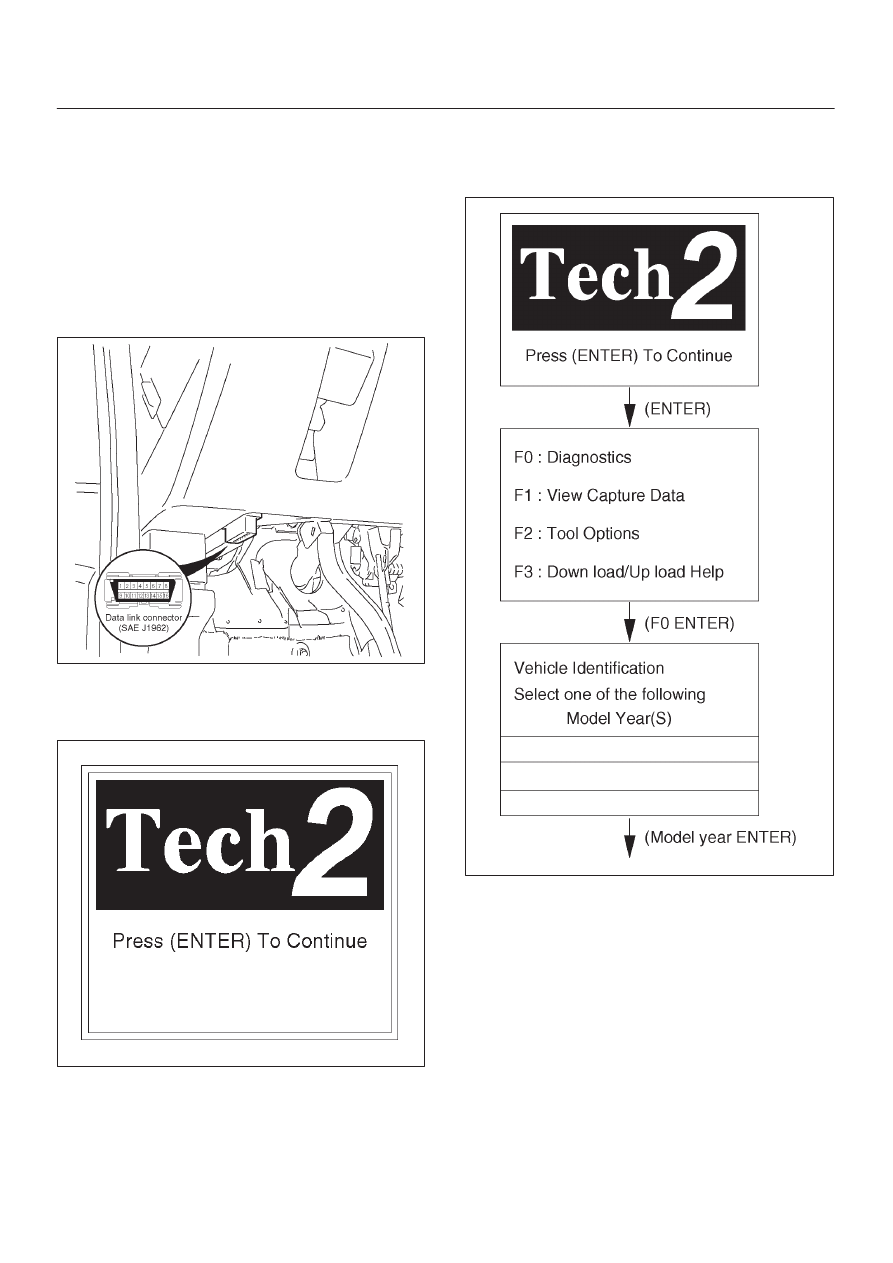
Operating Procedure
The power up screen is displayed when you power up the
tester with the Isuzu systems PCMCIA card. Follow the
operating procedure below.
060R100102