Isuzu Amigo / Axiom / Trooper / Rodeo / VehiCross. Manual - part 1579


  Index      Isuzu     Isuzu Amigo / Axiom / Trooper / Rodeo / VehiCross - service repair manual 1999-2002 year


Search            


Content   ..  1577  1578  1579  1580   ..


Isuzu Amigo / Axiom / Trooper / Rodeo / VehiCross. Manual - part 1579


TRANSMISSION CONTROL SYSTEM (4L30–E)

7A1–41

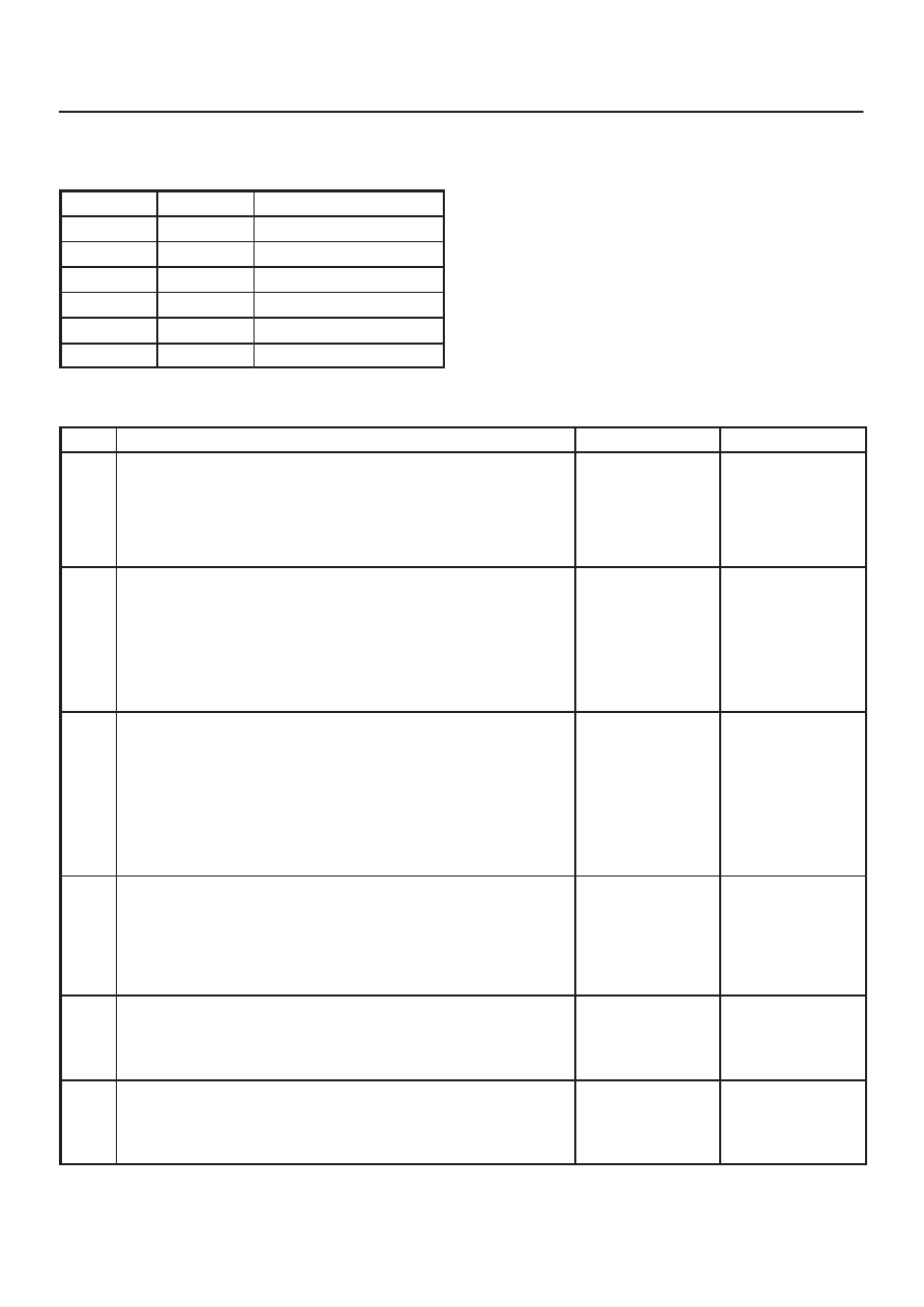
5. This test checks the TFT sensor and internal wiring

harness.

Resistance Chart

°

C

°

F

Resistance (k

W

)

–40

–40

672

0

32

65

20

68

25

80

176

2.5

120

248

0.78

150

304

0.37

DTC P0713 Transmission Fluid Temperature (TFT) Sensor Circuit High Input 

Step

Action

Yes

No

1

Were you sent here from the “Powertrain On–Board Diagnostic
(OBD) System Check”?

Go to Step 2

Go to OBD

System Check

Refer to

Driveability and

Emission in

Engine section

2

Perform the transmission fluid checking procedure.
Refer to Checking Transmission Fluid Level and Condition in
Automatic Transmission (4L30–E) section.

Was the fluid checking procedure performed?

Go to Step 3

Refer to

Checking

Transmission

Fluid Level and

Condition in

Automatic

Transmission

(4L30–E) section

3

1. Install the scan tool.
2. With the engine “off”, turn the ignition switch “on”.

NOTE: Before clearing DTC(s), use the scan tool to record “Freeze
Frame” and “Failure Records” for reference, as data will be lost
when the “Clear Info” function is used.

3. Record the DTC “Freeze Frame” and “Failure Records”.

Does the scan tool display a TFT sensor signal voltage greater
than 4.86 volts?

Go to Step 4

Go to Diagnostic

Aids

4

1. Turn the ignition “off”.
2. Disconnect the transmission 7–way connector E–54.
3. Install a fused jumper wire from terminal E54–4(F) to

E54–1(E) on the engine harness.

4. Turn the ignition “on”.

Does the TFT signal voltage drop to less than 0.4 volts?

Go to Step 5

Go to Step 10

5

1. Turn the ignition “off”.
2. Using the J39200 DVOM, measure the resistance between

terminals E54–4(F) and E54–1(E).

Is the resistance within specifications? (See Resistance Chart.)

Go to Diagnostic

Aids

Go to Step 6

6

1. Disconnect the transmission 7–way connector E–54.
2. Using the J39200 DVOM, measure the resistance between

terminals E54–4(F) and E54–1(E).

Is the resistance within specifications? (See Resistance Chart.)

Go to Diagnostic

Aids

Go to Step 7

7A1–42 TRANSMISSION CONTROL SYSTEM (4L30–E)

DTC P0713 Transmission Fluid Temperature (TFT) Sensor Circuit High Input  (Cont’d)

Step

No

Yes

Action

7

1. Remove the transmission oil pan.
2. Check the internal wiring harness for an open. Refer to

Transmission Oil Temperature Sensor (Main Case) in
Automatic Transmission (4L30–E) section.

Was a problem found and corrected?

Go to Step 14

Go to Step 8

8

1. Disconnect the internal wiring harness at the TFT sensor.
2. Measure the resistance of the TFT sensor.

Is the resistance within specifications? (See Resistance Chart.)

Go to Diagnostic

Aids

Go to Step 9

9

Replace TFT sensor. Refer to Transmission Oil Temperature
Sensor (Main Case) in Automatic Transmission (4L30–E)
section.

Is the replacement complete?

Go to Step 14

10

Check circuit RED/BLK for an open or short to B+.

Was a problem found?

Go to Step 14

Go to Step 11

11

Check circuit RED/WHT for an open.

Was a problem found?

Go to Step 14

Go to Step 12

12

Check the PCM for faulty or intermittent connections.

Was a problem found?

Go to Step 14

Go to Step 13

13

Replace the PCM. Refer to Powertrain Control Module (PCM) in
Automatic Transmission (4L30–E) section.

Is the replacement complete?

Go to Step 14

14

1. After the repair is complete, use the scan tool to select “DTC”,

then “Clear Info” function and ensure the following conditions
are met:

2. TFT sensor indicates a voltage less than 4.92 volts for 2

seconds.

3. Review the scan tool “DTC Info”.

Has the last test failed or is the current DTC displayed?

Begin diagnosis

again

Go to Step 1

Repair verified
Exit DTC table

TRANSMISSION CONTROL SYSTEM (4L30–E)

7A1–43

DTC P0719 Brake Switch Circuit Low (Stuck On)

D07R100018

Circuit Description:

The brake switch indicates brake pedal status to the
Powertrain Control Module (PCM). The brake switch is a
normally–closed switch that supplies battery voltage on
circuit GRY/RED–BRN/RED to the PCM. Applying the
brake pedal opens the switch, interrupting voltage to the
PCM. When the brake pedal is released, the PCM
receives a constant voltage signal. If the PCM receives a
zero voltage signal at the brake switch input, and the
Torque Converter Clutch (TCC) is engaged, the PCM
de–energizes the Torque Converter Clutch Solenoid
Valve (TCC Sol. Valve). The PCM disregards the brake
switch input for TCC scheduling if there is a brake switch
circuit fault (Refer to Diagnostic Aids).
When the PCM detects an open brake switch circuit (0
volts, low input) during accelerations, then DTC P0719
sets. DTC P0719 is a type D DTC.

Conditions For Setting The DTC

D

No OSS Assy. DTCs P0722 or P0723.

D

The PCM detects an open brake switch or circuit (0
volts) for 15 minutes without changing for 2 seconds,
and the following events occur seven consecutive
times.

D

The vehicle speed is less than 8 km/h (5 mph).

D

then the vehicle speed is 8–32 km/h (5–20 mph) for
4 seconds.

D

then the vehicle speed is greater than 32 km/h (20
mph) for 4 seconds.

Action Taken When The DTC Sets

D

The PCM does not illuminate the Malfunction
Indicator Lamp (MIL).

D

DTC P0719 stores in PCM history.

Conditions For Clearing The DTC

D

A scan tool can clear the DTC from the PCM history.
The PCM clears the DTC from the PCM history if the
vehicle completes 40 warm–up cycles without a
failure reported.

D

The PCM cancels the DTC default actions when the
fault no longer exists and the ignition is OFF long
enough in order to power down the PCM.

Diagnostic Aids

D

Inspect the wiring for poor electrical connections at
the PCM and brake switch. Look for possible bent,
backed out, deformed or damaged terminals. Check
for weak terminal tension as well. Also check for a
chafed wire that could short to bare metal or other
wiring. Inspect for a broken wire inside the insulation.

D

When diagnosing for a possible intermittent short or
open condition, move the wiring harness while
observing test equipment for a change.

D

Check customer driving habits and/or unusual driving
conditions (i.e. stop and go, highway).

D

Check brake switch for proper mounting and
adjustment.

7A1–44 TRANSMISSION CONTROL SYSTEM (4L30–E)

Test Description

The numbers below refer to the step numbers on the
diagnostic chart.
3. This step isolates the brake switch as a source for

setting the DTC.


Content   ..  1577  1578  1579  1580   ..