Isuzu Amigo / Axiom / Trooper / Rodeo / VehiCross. Manual - part 1572


  Index      Isuzu     Isuzu Amigo / Axiom / Trooper / Rodeo / VehiCross - service repair manual 1999-2002 year


Search            


Content   ..  1570  1571  1572  1573   ..


Isuzu Amigo / Axiom / Trooper / Rodeo / VehiCross. Manual - part 1572


TRANSMISSION CONTROL SYSTEM (4L30–E)

7A1–13

5. If problem solved: Go to CHECK TRANS

INDICATOR.

NO: Replace Powertrain Control Module (PCM).

D07RY00028

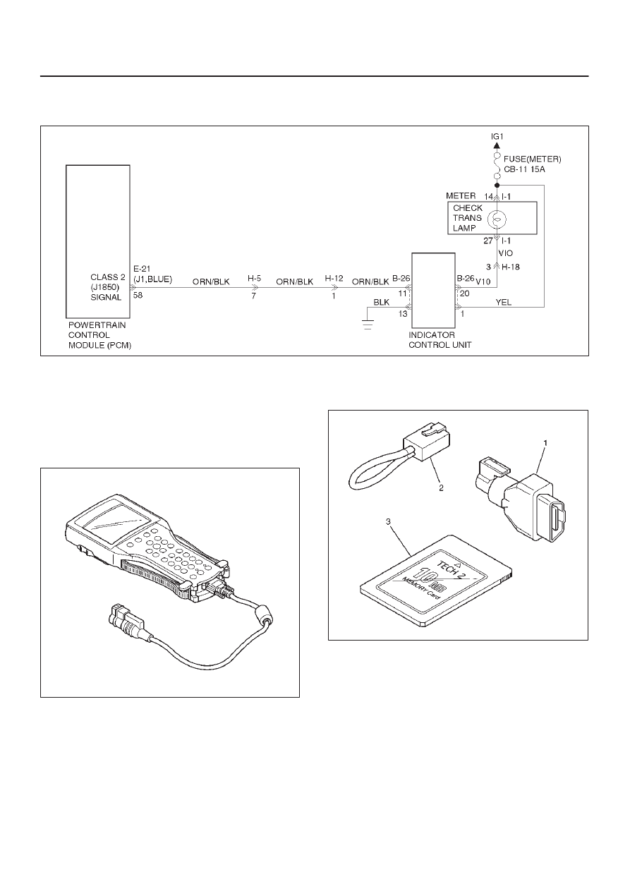
Tech 2 OBD II Connection

In order to access OBD II Powertrain Control Module
(PCM) data, use of the Tech 2 scan tool kit (7000086) is
required.

1. The electronic diagnosis equipment is composed of:

1. Tech 2 hand held scan tool unit (7000057) and

DLC cable (3000095).

901RW176

2. SAE 16/19 Pin Adapter (3000098)(1), RS232

Loop Back Connector (3000112)(2), and
PCMCIA Card (3000117)(3).

F07RW033

7A1–14 TRANSMISSION CONTROL SYSTEM (4L30–E)

2. Connecting the Tech 2

901RW180

Legend

(1) PCMCIA Card
(2) RS 232 Loop Back Connector

(3) SAE 16/19 Adapter
(4) DLC Cable
(5) Tech 2

D

Before operating the Isuzu PCMCIA card with the
Tech 2, the following steps must be performed:

1. The Isuzu 2001 System PCMCIA card (1) inserts

into the Tech 2 (5).

2. Connect the SAE 16/19 adapter (3) to the DLC

cable (4).

3. Connect the DLC cable to the Tech 2 (5)

4. Mark sure the vehicle ignition is off.

TRANSMISSION CONTROL SYSTEM (4L30–E)

7A1–15

5. Connect the Tech 2 SAE 16/19 adapter to the

vehicle DLC.

740RW060

6. The vehicle ignition turns on.

7. Verify the Tech 2 power up display.

060RW009

NOTE: The RS232 Loop back connector is only to use for
diagnosis of Tech 2 and refer to user guide of the Tech 2.

8. The power up screen is displayed when you

power up the tester with the Isuzu systems
PCMCIA card. Follow the operating procedure
below.

060R100074

7A1–16 TRANSMISSION CONTROL SYSTEM (4L30–E)

060R100075

Once the test vehicle has been identified an “Application
(Powertrain) Menu” screen appears. Please select the
appropriate application.
The following table shows, which functions are used for
the available equipment versions.

F0: Diagnostic Trouble Codes

F0: Read DTC Info Ordered By Priority

F1: Clear DTC Information

F2: DTC Information

F1: Data Display

F0: Transmission Data

F2: Snap Shot

F3: Actuator Tests

F0: Lamps

F0: Check Light

F1: Winter Drive Lamp

F2: Power Drive Lamp

F3: AT Oil Temperature Lamp

F1: Solenoids

F0: Solenoid 1-2/3-4 Test

F1: Solenoid 2-3 Test

F2: TCC Solenoid

F3: Band Apply Solenoid

F4: Pressure Control Solenoid (PCS)

F4: Function Tests

F0: Reset Oil Life Monitor


Content   ..  1570  1571  1572  1573   ..