Isuzu Amigo / Axiom / Trooper / Rodeo / VehiCross. Manual - part 1537


  Index      Isuzu     Isuzu Amigo / Axiom / Trooper / Rodeo / VehiCross - service repair manual 1999-2002 year


Search            


Content   ..  1535  1536  1537  1538   ..


Isuzu Amigo / Axiom / Trooper / Rodeo / VehiCross. Manual - part 1537


6G–5

ENGINE LUBRICATION (6VD1 3.2L)

D

Measure the side clearance with a precision straight
edge and a feeler gauge.

Clearance
Standard : 0.03 mm–0.09 mm

(0.0011 in–0.0035 in)

Limit : 0.15mm (0.0059 in)

051RS005

Oil Strainer

Check the oil strainer for cracking and scoring. If cracking
and scoring are found, the oil strainer must be replaced.

051RS006

Reassembly

1. Install drive gear (11).
2. Install driven gear (10).
3. Install oil pump cover (9) and first, loosely tighten all of

the attaching screws. Next, tighten the attaching
screws to the specified torque.

Torque : 10 N·m (87 lb in)

After installation, check that the gear rotates
smoothly.

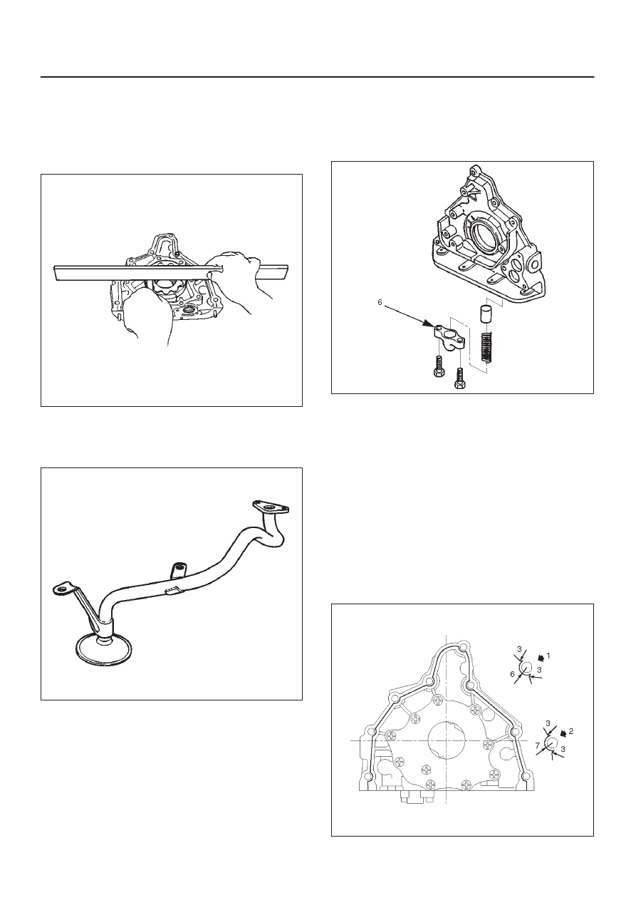
4. Install relief valve (8) and apply engine oil to the relief

valve and spring (7).

5. Install spring (7).
6. Install the plug (6).

Torque : 8 N·m (69 lb in)

051RS007

7. Install oil pump assembly (5).

D

Carefully remove any oil from the cylinder body and
the pump. Apply sealant (TB–1207B or equivalent)
to the pump fitting face as shown in illustration. Take
care that sealant is not applied to oil port surfaces.
The oil pump assembly must be installed within 5
minutes after sealant application to prevent
premature hardening of sealant.

CAUTION: Do not apply an excessive amount of
sealant to the contact surface. Applying too much
sealant will overflow the contact surfaces. This
could cause serious damage to the engine.

D

Attach oil pump assembly to cylinder body.

D

Tighten the oil pump fixing bolts.

Torque : 25 N·m (18 lb·ft)

051RW002

6G–6

ENGINE LUBRICATION (6VD1 3.2L)

051RW001

Legend

(1) Around Bolt Holes
(2) Around Dowel Pin

8. Install the new oil seal (12). Apply engine oil to the oil

seal lip before installation then use J–39202 oil seal
Installer, install oil seal.

015RS001

9. Install oil strainer (4) with O-ring (13).

Torque: 25 N·m (18 lb ft)

10. Install oil pipe (3) with O-ring (13).

Torque: 25 N·m (18 lb ft)

11. Install crankcase with oil pan (2).

D

Remove oil on crankcase mounting surface and dry
the surface.

D

Apply a proper 4.5 mm (0.7 in) wide bead of sealant
(TB1207C or equivalent) to the crankcase
mounting surface. The bead must be continuous.

D

The crankcase must be installed within 5 minutes
after sealant application to prevent premature
hardening of sealant.

D

Tighten fixing bolts to the specified torque.

Torque : 10 N·m (87 lb in)

013RW010

12. Install crankshaft timing pulley.

6G–7

ENGINE LUBRICATION (6VD1 3.2L)

Oil Pan and Crankcase

Removal

1. Disconnect battery ground cable.
2. Lift vehicle by supporting the frame.
3. Remove under cover.
4. Drain engine oil.
5. Remove front wheels.
6. Remove oil level dipstick from level gauge tube.
7. Remove radiator under fan shroud.
8. Remove shift on the fly from axle housing.
9. Remove suspension cross member fixing bolts, 2 pcs

each per side and remove suspension cross member.

10. Remove axle housing assembly four fixing bolts from

housing isolator side and mounting bolts from wheel
side. At this time support the axle with a garage jack
and remove axle housing assembly. (for 4

×

4)

11. Remove the steering unit assembly.

12. Remove starter fixing bolts.
13. Remove oil pan fixing bolts.
14. Remove oil pan, using J-37228 sealer cutter, remove

oil pan.

013RS003

15. Remove crankcase fixing bolts.
16. Remove crankcase, using J-37228 sealer cutter,

remove crankcase.

NOTE: Do not deform or damage the flange of oil pan and
crankcase.
Replace the oil pan and/or crankcase if deformed or dam-
aged.

013RS003

Installation

1. Install crankcase.

A. Remove residual sealant, lubricant and moisture

from mounting surface, then dry thoroughly.

B. Properly apply a 4.5 mm (0.7 in) wide bead of

sealant (TB-1207C or equivalent) to mounting
surface of crankcase.

Sealant bead must be continuous.

D

The crankcase must be installed within 5 minutes
after sealant application to prevent premature
hardening of sealant.

013RW010

6G–8

ENGINE LUBRICATION (6VD1 3.2L)

C. Install crankcase, tighten crankcase fixing bolts to

the specified torque.

Torque : 10 N·m (87 lb in)

013RW004

2. Install oil pan

A. Remove residual sealant, lubricant and moisture

from mounting surface, then dry thoroughly.

B. Properly apply a 4.5 mm (0.7 in) wide bead of

sealant (TB-1207C or equivalent) to mounting
surface of oil pan.

Sealant beat must be continuous.

D

The crankcase must be installed within 5 minutes
after sealant application to prevent premature
hardening of sealant.

013RW003

C. Install oil pan, tighten oil pan fixing bolts to the

specified torque.

Torque : 10 N·m (87 lb in)

3. Install starter and tighten fixing bolts.

Torque: 40 N·m (30 lb ft)

4. Install axle housing assembly and tighten fixing bolts

to the specified torque. (for 4

×

4)

Axle case bolts
Torque : 82 N·m (61 lb ft)
Mounting bolts
Torque : 152 N·m (112 lb ft)

013RW005

5. Install the shift on the fly.
6. Install relay lever assembly and tighten fixing bolts.

Torque: 44 N·m (33 lb ft)

7. Install suspension cross member and tighten fixing

bolts to the specified torque.

Torque : 78 N·m (58 lb ft)

013RW007

8. Install radiator under fan shroud.
9. Install under cover.

10. Install engine oil level dipstick.

11. Fill engine oil until full level on engine oil gauge

dipstick.


Content   ..  1535  1536  1537  1538   ..