Isuzu Amigo / Axiom / Trooper / Rodeo / VehiCross. Manual - part 1521


  Index      Isuzu     Isuzu Amigo / Axiom / Trooper / Rodeo / VehiCross - service repair manual 1999-2002 year


Search            


Content   ..  1519  1520  1521  1522   ..


Isuzu Amigo / Axiom / Trooper / Rodeo / VehiCross. Manual - part 1521


6E2–535

RODEO 6VD1 3.2L ENGINE DRIVEABILITY AND EMISSIONS

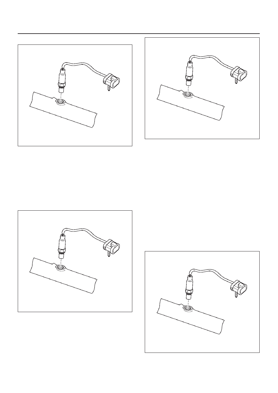
3. Disconnect the pigtail from the wiring harness.

060RY00128

IMPORTANT:

The pigtail is permanently attached to

the sensor.  Be careful not to pull the wires out.

NOTE: Do not use a torch to remove an HO2S unless the
sensor is being replaced.  Using a torch could damage the
sensor.

4. Remove the sensor from the exhaust pipe.

D

Because of the expansion and contraction of the
metal in the exhaust system over time, this may be
difficult if the engine temperature is below 48

°

C

(120

°

F).

060RY00128

Inspection Procedure

All four sensors are identical.  Inspect each in the same
way.

1. Inspect the pigtail and the electrical connector for

grease, dirt, corrosion, and bare wires or worn
insulation.

2. Inspect the louvered end of the sensor for grease,

dirt, or other contaminations.

060RY00128

Installation Procedure

IMPORTANT:

D

There is a special anti-seize compound on the HO2S
threads.  This compound consists of glass beads
suspended in a liquid graphite solution.  The graphite
burns away with engine heat, but the glass beads will
remain, making the sensor easier to remove.

D

New or service sensors will already have the
compound applied to the threads.  If a sensor is
removed and is to be reinstalled for any reason, the
threads must have anti-seize compound applied.

1. Apply anti-seize compound or the equivalent to the

threads of the oxygen sensor, if necessary.

2. Install the oxygen sensor on the exhaust pipe in its

original position.

Tighten

D

Tighten the oxygen sensor to 55 N·m (40 lb ft.).

060RY00128

3. Connect the pigtail to the wiring harness.
4. Connect the negative battery cable.

6E2–536

RODEO 6VD1 3.2L ENGINE DRIVEABILITY AND EMISSIONS

Intake Air Temperature (IAT)

Sensor

Removal Procedure

1. Disconnect the negative battery cable.
2. Remove the engine cover
3. The IAT sensor is located in the intake air duct, behind

the throttle body.

4. Disconnect the electrical connector from the IAT

sensor.

TS23741

5. Remove the IAT sensor from the intake air duct by

using a rocking motion while pulling the sensor.

Installation Procedure

1. Install the IAT sensor into the grommet in the intake

air duct.

2. Correct the IAT electrical connector.

TS23741

3. Install the engine cover.
4. Connect the negative battery cable.

ION Sensing Module

Removal Procedure

1. Disconnect the negative battery cable.
2. Disconnect the ION sensing module connector.
3. Remove the bolts and the ION sensing module from

the common chamber.

060RY00087

Installation Procedure

1. Install the ION sensing module on the common

chamber with the bolts.

Tighten

D

Tighten the ION sensing module to 4 N·m (35 lb
in.).

6E2–537

RODEO 6VD1 3.2L ENGINE DRIVEABILITY AND EMISSIONS

2. Connect the ION sensing module connectors as

shown in the illustration.

060RY00003

Legend

(1) Green Color Connector
(2) Blue Color Connector

3. Connect the negative battery cable.

Mass Air Flow (MAF) Sensor

Removal Procedure

1. Disconnect the negative battery cable.
2. Disconnect the electrical connector from the MAF

sensor.

TS23740

3. Loosen the clamps which secure the intake air duct

and the air cleaner to the MAF sensor.

4. Remove the intake air duct from the MAF sensor.
5. Remove the MAF sensor from the air cleaner.

TS23781

Installation Procedure

1. Install the MAF sensor on the air cleaner with the

clamp.

2. Install the intake air duct and the clamp on the MAF

sensor.

TS23781

3. Tighten the clamps to secure the MAF sensor to the

intake air duct and the air cleaner.

4. Connect the MAF electrical connector.
5. Connect the negative battery cable.

6E2–538

RODEO 6VD1 3.2L ENGINE DRIVEABILITY AND EMISSIONS

Manifold Absolute Pressure

(MAP) Sensor

Removal Procedure

1. Disconnect the negative battery cable.
2. Disconnect the electrical connector from the MAP

sensor.

055RY00001

3. Remove the bolt securing the MAP sensor to the

mounting bracket on the common chamber.

4. Remove the MAP sensor from the mounting bracket.

055RW002

Installation Procedure

1. Install the MAP sensor in the mounting bracket.

055RW002

2. Install the mounting bracket retaining bolt on the

common chamber.

Tighten

D

Tighten the bolt to 20 N·m (12 lb ft.).

3. Connect the MAP electrical connector.

055RY00001

4. Connect the negative battery cable.


Content   ..  1519  1520  1521  1522   ..