Isuzu Amigo / Axiom / Trooper / Rodeo / VehiCross. Manual - part 1435


  Index      Isuzu     Isuzu Amigo / Axiom / Trooper / Rodeo / VehiCross - service repair manual 1999-2002 year


Search            


Content   ..  1433  1434  1435  1436   ..


Isuzu Amigo / Axiom / Trooper / Rodeo / VehiCross. Manual - part 1435


6E2–191

RODEO 6VD1 3.2L ENGINE DRIVEABILITY AND EMISSIONS

Diagnostic Trouble Code (DTC) 

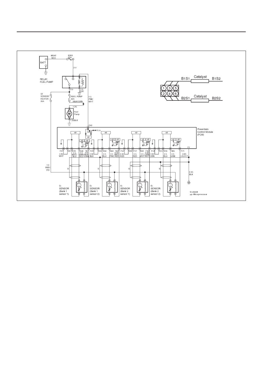
P0141 HO2S Heater Circuit Bank 1 Sensor 2

060R200054

Circuit Description

Heated oxygen sensors are used to minimize the amount
of time required for closed loop fuel control operation and
to allow accurate catalyst monitoring.  The oxygen sensor
heater greatly decreases the amount of time required for
fuel control sensors Bank 1 HO2S 1 and Bank 2 HO2S 1
to become active.  Oxygen sensor heaters are required
by post-catalyst monitor sensors to maintain a sufficiently
high temperature which allows accurate exhaust oxygen
content readings further from the engine.
The powertrain control module (PCM) will run the heater
test only after a cold start (determined by engine coolant
and intake air temperature at the time of start-up) and only
once during an ignition cycle.  When the engine is started
the PCM will monitor the HO2S voltage.  When the Bank
HO2S voltage indicates a sufficiently active sensor, the
PCM looks at how much time has elapsed since start-up.
If the PCM determines that too much time was required
for the Bank 1 HO2S 2 to become active, a DTC P0141
will set.  The time it should take the HO2S to reach
operating temperature is based on the total amount of air
that has passed through the MAF sensor and into the
engine (more total airflow = shorter time to HO2S
activity).

Conditions for Setting the DTC

D

No related DTCs.

D

The engine has been running for over 120 seconds.

D

Ignition voltage is between 11 volts and 18 volts.

D

Bank 1 HO2S 2 voltage does not change more than
150 mV from the bias voltage (between
400 mV–500 mV) for a longer amount of time than it
should.  The maximum amount of time to come up to
operating range is 120 seconds.  This warm-up time
depends on the engine coolant temperature at start-up
and accumulated air flow since start-up.

Action Taken When the DTC Sets

D

The PCM will illuminate the malfunction indicator lamp
(MIL) after the second consecutive trip in which the
fault is detected.

D

The PCM will store conditions which were present
when the DTC was set as Freeze Frame and in the
Failure Records data.

Conditions for Clearing the MIL/DTC

D

The PCM will turn the MIL “OFF” on the third
consecutive trip cycle during which the diagnostic has
been run and the fault condition is no longer present.

D

A history DTC P0141 will clear after 40 consecutive
warm-up cycles have occurred without a fault.

D

DTC P0141 can be cleared by using the Tech 2 “Clear
Info” function or by disconnecting the PCM battery
feed.

Diagnostic Aids

Check for the following conditions:

6E2–192

RODEO 6VD1 3.2L ENGINE DRIVEABILITY AND EMISSIONS

D

Poor connection at PCM – Inspect harness connectors
for backed-out terminals, improper mating, broken
locks, improperly formed or damaged terminals, and
poor terminal-to-wire connection.

D

Damaged harness – Inspect the wiring harness for
damage.  If the harness appears to be OK, observe the
display on the Tech 2 while moving connectors and
wiring harnesses related to the sensor.  A change in the
display will indicate the location of the fault.

Reviewing the Failure Records vehicle mileage since the
diagnostic test last failed may help determine how often
the condition that caused the DTC to be set occurs.  This
may assist in diagnosing the condition.

Test Description

Number(s) below refer to the step number(s) on the
Diagnostic Chart.

2. The HO2S should be allowed to cool before

performing this test.  If the HO2S heater is
functioning, the signal voltage will gradually increase
or decrease as the sensor element warms.  If the
heater is not functioning, the HO2S signal will
remain near the 450 mV bias voltage.

4. This ensures that the ignition feed circuit to the

HO2S is not open or shorted.  The test light should
be connected to a good chassis ground, in case the
HO2S low or HO2S heater ground circuit is faulty.

5. This checks the HO2S heater ground circuit.

6. This checks for an open or shorted HO2S heater

element.

11.An open HO2S signal or low circuit can cause the

HO2S heater to appear faulty.  Check these circuits
before replacing the sensor.

DTC P0141 – HO2S Heater Circuit Bank 1 Sensor 2


Step

Action

Value(s)

Yes

No

1

Was the “On-Board Diagnostic (OBD) System Check”
performed?

Go to 

Step 2

Go to 

OBD

System

Check

2

NOTE: If the engine has just been operating, allow the
engine to cool for at least 15 minutes before
proceeding.

1. Remove the fuel pump relay.
2. Connect a fused jumper at the fuel pump relay

socket, between the battery positive at the relay and
the relay wire that leads to the fuel pump and HO2S
fuses.

3. Ignition “OFF”.
4. Install a Tech 2.
5. Ignition “ON”, engine “OFF”.
6. Monitor the Bank 1 HO2S 2 voltage for several

minutes.

Did the HO2S voltage go from bias voltage to above or
below the specified values?

Above

650 mV or

below

250 mV

Refer to

Diagnostic

Aids

Go to 

Step 3

3

Inspect the fuse for Bank 1 HO2S 2 ignition feed.

Is the fuse open?

Go to 

Step 15

Go to 

Step 4

4

1. Ignition “OFF”.
2. Raise the vehicle.
3. Disconnect the Bank 1 HO2S 2 electrical connector.
4. Using a test light connected to a good ground (do

not use Bank 1 HO2S 2 heater ground or Bank 1
HO2S 2 low), probe the ignition feed circuit at the
Bank 1 HO2S 2 electrical connector (PCM harness
side).

Does the test light illuminate?

Go to 

Step 5

Go to 

Step 7

5

Connect the test light between the Bank 1 HO2S 2
ignition feed and the Bank 1 HO2S 2 heater ground.

Does the test light illuminate?

Go to 

Step 6

Go to 

Step 8

6E2–193

RODEO 6VD1 3.2L ENGINE DRIVEABILITY AND EMISSIONS

DTC P0141 – HO2S Heater Circuit Bank 1 Sensor 2

  (Cont'd)

Step

No

Yes

Value(s)

Action

6

1. Allow the HO2S to cool for at least 15 minutes.
2. Using a DVM, measure the resistance between the

Bank 1 HO2S 2 ignition feed and the Bank 1 HO2S 2
heater ground at the Bank 1 HO2S 2 pigtail.

Is the HO2S resistance within the specified values?

3-6 ohms

Go to 

Step 9

Go to 

Step 10

7

Repair the open Bank 1 HO2S 2 ignition feed circuit to
Bank 1 HO2S 2.

Is the action complete?

Verify repair

8

Repair the open Bank 1 HO2S 2 heater ground circuit.

Is the action complete?

Verify repair

9

1. Check for a poor connection at the Bank 1 HO2S 2

harness terminals.

2. If a poor connection is found, replace the terminals.

Was a poor connection found?

Verify repair

Go to 

Step 10

10

1. Ignition “OFF”.
2. Disconnect the PCM and check the continuity of the

Bank 1 HO2S 2 signal circuit and the Bank 1 HO2S
2 low circuit.

3. If the Bank 1 HO2S 2 signal circuit or the HO2S low

circuit measures over 5 ohms, repair the open or
poor connection as necessary.

Was a problem found?

Verify repair 

Go to 

Step 11

11

1. Ignition “OFF”.
2. Disconnect the PCM and check the continuity of the

Bank 1 HO2S 1 signal circuit and the Bank 1 HO2S
1 low circuit.

3. If the Bank 1 HO2S 1 high circuit or the HO2S low

circuit measures over 5 ohms, repair the open or
poor connection as necessary.

Was a problem found?

Verify repair

Go to 

Step 12

12

Check for a poor Bank 1 HO2S 2 low circuit terminal
connection at the PCM and replace the terminal if
necessary.

Did the terminal require replacement?

Verify repair

Go to 

Step 13

13

Check for a poor Bank 1 HO2S 2 high circuit terminal
connection at the PCM and replace the terminal if
necessary.

Did the terminal require replacement?

Verify repair

Go to 

Step 14

14

Replace Bank 1 HO2S 2.

Is the action complete?

Verify repair

15

Locate and repair the short to ground in Bank 1 HO2S 2
ignition feed circuit and replace the faulty fuse.

Is the action complete?

Verify repair

6E2–194

RODEO 6VD1 3.2L ENGINE DRIVEABILITY AND EMISSIONS

Diagnostic Trouble Code (DTC) 

P0151 HO2S Circuit Low Voltage Bank 2 Sensor 1

060R200054

Circuit Description

The powertrain control module (PCM) supplies a bias
voltage of about 450 mV between the heated oxygen
sensor (HO2S) signal high and signal low circuits.  When
measured with a 10 megaohm digital voltmeter, this may
display as low as 320 mV.  The oxygen sensor varies the
voltage within a range of about 1000 mV when the
exhaust is rich, down through about 10 mV when exhaust
is lean.  The PCM constantly monitors the HO2S signal
during “closed loop” operation and compensates for a rich
or lean condition by decreasing or increasing injector
pulse width as necessary.  If the Bank 2 HO2S 1 voltage
remains excessively low for an extended period of time,
DTC P0151 will be set.

Conditions for Setting the DTC

D

No related DTCs.

D

The engine is operating in “closed loop”.

D

Engine coolant temperature is above 60

°

C (140

°

F).

D

“Closed loop” commanded air/fuel ratio is between
14.5 and 14.8.

D

Bank 2 HO2S 1 signal voltage remains below 22 mV
during normal “closed loop” operation for a total of 77
seconds over a 90-second period of time.

Action Taken When the DTC Sets

D

The PCM will ON the MIL after second trip with
detected fault.

D

The PCM will store conditions which were present
when the DTC was set as Freeze Frame and in the
Failure Records data.

D

“Open loop” fuel control will be in effect.

Conditions for Clearing the MIL/DTC

D

The PCM will turn the MIL “OFF” on the third
consecutive trip cycle during which the diagnostic has
been run and the fault condition is no longer present.

D

A history DTC P0151 will clear after 40 consecutive
warm-up cycles have occurred without a fault.

D

DTC P0151 can be cleared by using the Tech 2 “Clear
Info” function or by disconnecting the PCM battery
feed.

Diagnostic Aids

Check for the following conditions:

D

Heated oxygen sensor wiring – The sensor pigtail may
be mispositioned and contacting the exhaust system.

D

Poor PCM to engine block grounds.

D

Fuel pressure – The system will go lean if pressure is
too low.  The PCM can compensate for some
decrease.  However, if fuel pressure is too low, a DTC
P0151 may be set.  Refer to 

Fuel System Diagnosis.

D

Lean injector(s) – Perform “Injector Balance Test”.

D

Vacuum leaks – Check for disconnected or damaged
vacuum hoses and for vacuum leaks at the intake
manifold, throttle body, EGR system, and PCV system.


Content   ..  1433  1434  1435  1436   ..