Isuzu Amigo / Axiom / Trooper / Rodeo / VehiCross. Manual - part 1362


  Index      Isuzu     Isuzu Amigo / Axiom / Trooper / Rodeo / VehiCross - service repair manual 1999-2002 year


Search            


Content   ..  1360  1361  1362  1363   ..


Isuzu Amigo / Axiom / Trooper / Rodeo / VehiCross. Manual - part 1362


6A–52

ENGINE MECHANICAL (6VD1 3.2L)

Valve Spring, Oil Controller, Valve, Valve Guide

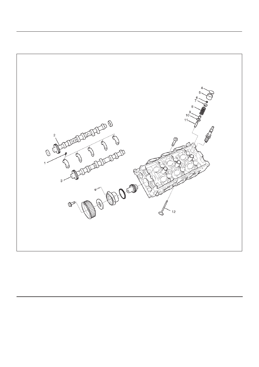
Valve Spring, Oil Controller, Valve, Valve Guide and Associated Parts

014RW039

Legend

(1) Camshaft Bearing Cap Fixing Bolts
(2) Camshaft Assembly Inlet
(3) Camshaft Assembly Exhaust
(4) Shim
(5) Tappet
(6) Split Collar

(7) Spring Upper Seat
(8) Valve Spring
(9) Oil Controller

(10) Spring Lower Seat

(11) Valve Guide

(12) Valve

Disassembly

1. Remove camshaft bearing cap fixing bolts (1).
2. Remove camshaft assembly (intake).

3. Remove camshaft assembly (Exhaust side).
4. Remove shim (4) and tappet (5).

6A–53

ENGINE MECHANICAL (6VD1 3.2L)

5. Use the J–8062 valve spring compressor and

J–42898 valve spring compressor adapter to remove
split collar.

014RW042

6. Remove valve spring.
7. Remove valve.
8. Remove oil controller and spring lower seat.
9. Remove the valve guide using the J–42899 valve

guide replacer.

Inspection and Repair

Valve Spring

CAUTION: Visually inspect the valve springs and
replace them if damage or abnormal wear is evident.

1. Measure the free height of the springs. The springs

must be replaced if the free height is below the
specified limit.

Standard : 44.6 mm (1.756 in)
Limit : 43.6 mm (1.717 in)

014RS004

2. Measure the valve spring squareness with a steel

square and replace the valve springs if the measured
value exceeds the specified limit.

Limit : 2 mm (0.079 in)

014RS005

3. Using a spring tester to compress the springs to the

installed height, measure the compressed spring
tension, and replace the springs if the measured
tension is below the specified limit.

At installed height: 35.0 mm (1.38 in)
Standard: 196 N (44 lb)
Limit: Less than 181 N (41 lb)

014RS006

Valve Guide

CAUTION: Take care not to damage the valve seat
contact surface, when removing carbon adhering to
the valve head. Carefully inspect the valve stem for
scratchs or abnormal wear. If these conditions are
present, the valve and the valve guide must be
replaced as a set.

6A–54

ENGINE MECHANICAL (6VD1 3.2L)

1. Measure the valve stem diameter with a micrometer.

If the valve stem diameter is less than the specified
limit, the valve and the valve guide must be replaced
as a set.

Diameter of Valve Stem
Intake
Standard : 5.977 mm–5.959 mm

(0.2353 in–0.2346 in)

Limit : 5.90 mm (0.2323 in)
Exhaust
Standard : 5.952 mm–5.970 mm

(0.2343 in–0.2350 in)

Limit : 5.90 mm (0.2323 in)

014RS007

2. Measure the inside diameter of the valve guide with a

micrometer. Subtract the measured outer diameter of
the valve stem from the measured inner diameter of
the valve guide. If the value exceeds the specified
limit, the valve and the valve guide must be replaced
as a set.

Inside Diameter of the Vale Guide
Inlet clearance
Standard : 0.023 mm–0.056 mm

(0.0009 in–0.0002 in)

Limit : 0.20 mm (0.00787 in)
Exhaust clearance
Standard : 0.030 mm–0.063 mm

(0.0012 in–0.0025 in)

Limit : 0.20 mm (0.00787 in)

Valve Guide Replacement

1. Using Valve guide replacer: J–42899, drive out the

valve guide from the combustion chamber side.

014RS008

2. Apply engine oil to the outside of the valve guide.

Using valve guide replacer J–42899, drive in a new
valve guide from the camshaft side, and check the
valve guide height.

Valve guide upper end height: 13.0 mm (0.5118
in)

(Measured from the cylinder head upper face)

014RW046

3. Check the clearance. If the clearance is less than the

specified value, ream the inside diameter of valve
guide. Using a sharp 6 mm reamer, ream the valve
guide to obtain the specified clearance.

6A–55

ENGINE MECHANICAL (6VD1 3.2L)

Valve Seat

1. Measure the protrusion of the valve stem when a new

valve is installed in the cylinder head. If the protrusion
of the valve stem exceeds the limit, replace the valve
seat insert or the cylinder head assembly.

Protrusion of valve stem
Intake
Standard: 39.32 mm (1.5480 in)
Limit: 39.47 mm (1.5539 in)
Exhaust
Standard: 39.3 mm (1.5472 in)
Limit: 39.45 mm (1.5531 in)

014RW047

2. Measure the valve seat contact width. Make the

necessary corrections if the seat contact surface is
damaged or rough or if the contact width wear
exceeds the limit.

Valve seat contact width
Standard: 1.1 mm (0.0433 in)
Limit: 1.7 mm (0.0669 in)

014RS011

Contact Surface Angle on Valve Seat on
Valve

1. Measure contact surface angle on valve seat.
2. If the measured value exceeds the limit, replace

valve, valve guide and valve seat as a set.

Valve contact surface angle: 45

°

014RS012

Valve Seat Insert Correction

1. Remove the carbon from the valve seat insert

surface.

2. Use a valve cutter to minimize scratches and other

rough areas. This will bring the contact width back to
the standard value. Remove only the scratches and
rough areas. Do not cut away too much. Take care not
to cut away unblemished areas of the valve seat
surface.

Valve seat angle degree: 90

°

014RW059


Content   ..  1360  1361  1362  1363   ..