Content .. 1341 1342 1343 1344 ..
Isuzu Amigo / Axiom / Trooper / Rodeo / VehiCross. Manual - part 1343
6E1–448
RODEO Y22SE 2.2L ENGINE DRIVEABILITY AND EMISSION
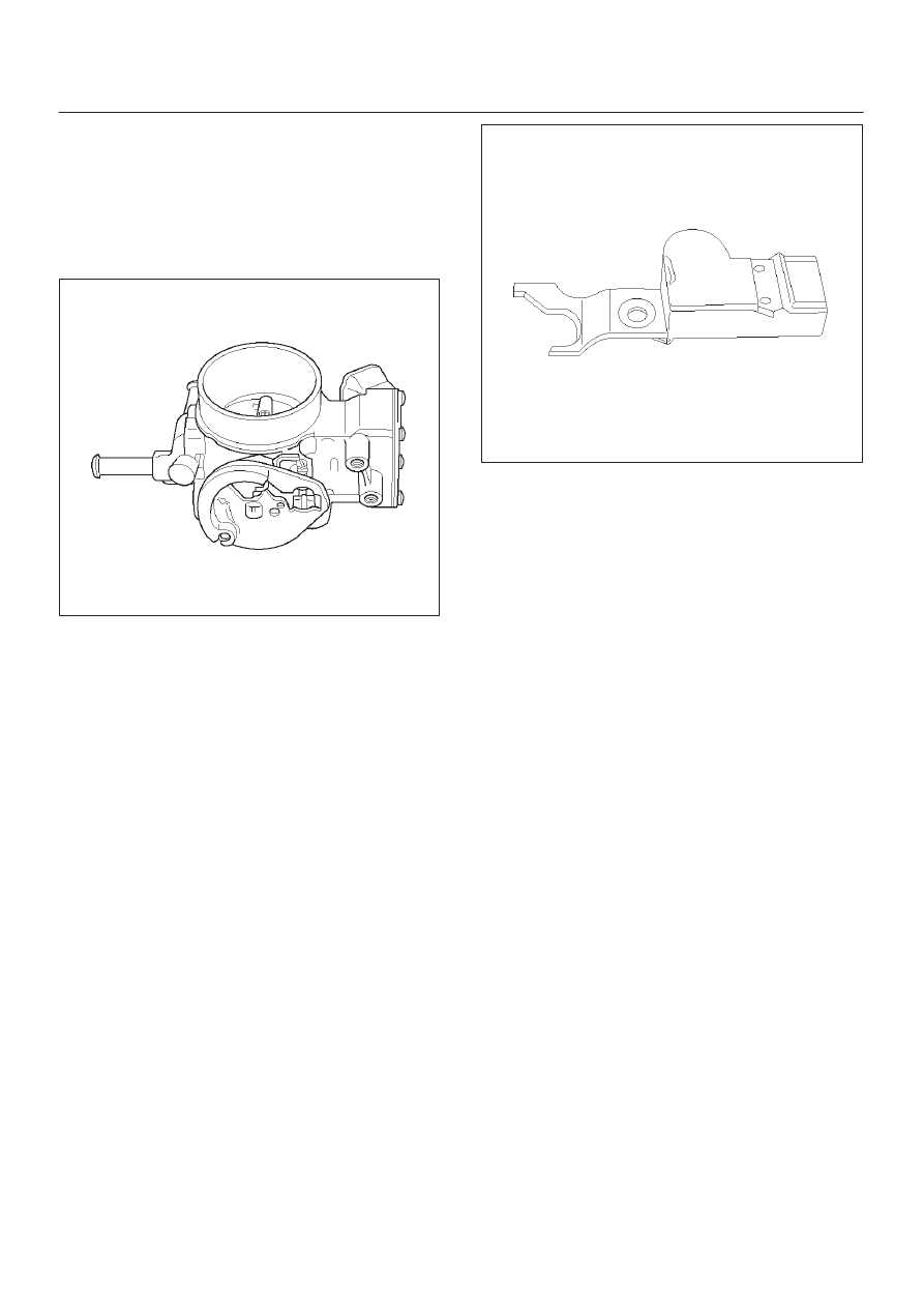
Throttle Body Unit
The throttle body has a throttle plate to control the amount
of air delivered to the engine. The TP sensor and IAC
valve are also mounted on the throttle body.
Vacuum ports located behind the throttle plate provide the
vacuum signals needed by various components. Engine
coolant is directed through a coolant cavity in the throttle
body to warm the throttle valve and to prevent icing.
014RX040
GENERAL DESCRIPTION —
ELECTRONIC IGNITION SYSTEM
Camshaft Position (CMP) Sensor
The camshaft position (CMP) sensor sends a signal to
the PCM. The PCM uses this signal as a ”sync pulse” to
trigger the injectors in the proper sequence. The PCM
uses the CMP signal to indicate the position of the #1
piston during its power stroke. The CMP allows the PCM
to calculate true sequential fuel injection (SFI) mode of
operation. If the PCM detects an incorrect CMP signal
while the engine is running, DTC P0341 will set.
If the CMP signal is lost while the engine is running, the
fuel injection system will shift to a calculated sequential
fuel injection mode based on the last fuel injection pulse,
and the engine will continue to run. It will run in the
calculated sequential mode with a 1–in–4 chance of the
injector being correct.
For additional information, refer to DTC P0342.
014RX007
Crankshaft Position (CKP) Sensor
The crankshaft position (CKP) sensor provides a signal
used by the powertrain control module (PCM) to calculate
the ignition sequence. The sensor initiates the 58X
reference pulses which the PCM uses to calculate RPM
and crankshaft position. For additional information, refer
to Electronic Ignition System.
Electronic Ignition
The electronic ignition system controls fuel combustion
by providing a spark to ignite the compressed air/fuel
mixture at the correct time. To provide optimum engine
performance, fuel economy, and control of exhaust
emissions, the PCM controls the spark advance of the
ignition system. Electronic ignition has the following
advantages over a mechanical distributor system:
D
No moving parts.
D
Less maintenance.
D
Remote mounting capability.
D
No mechanical load on the engine.
D
More coil cooldown time between firing events.
D
Elimination of mechanical timing adjustments.
D
Increased available ignition coil saturation time.