Isuzu Amigo / Axiom / Trooper / Rodeo / VehiCross. Manual - part 134


  Index      Isuzu     Isuzu Amigo / Axiom / Trooper / Rodeo / VehiCross - service repair manual 1999-2002 year


Search            


Content   ..  132  133  134  135   ..


Isuzu Amigo / Axiom / Trooper / Rodeo / VehiCross. Manual - part 134


4C–36

DRIVE SHAFT SYSTEM

Rear Propeller Shaft

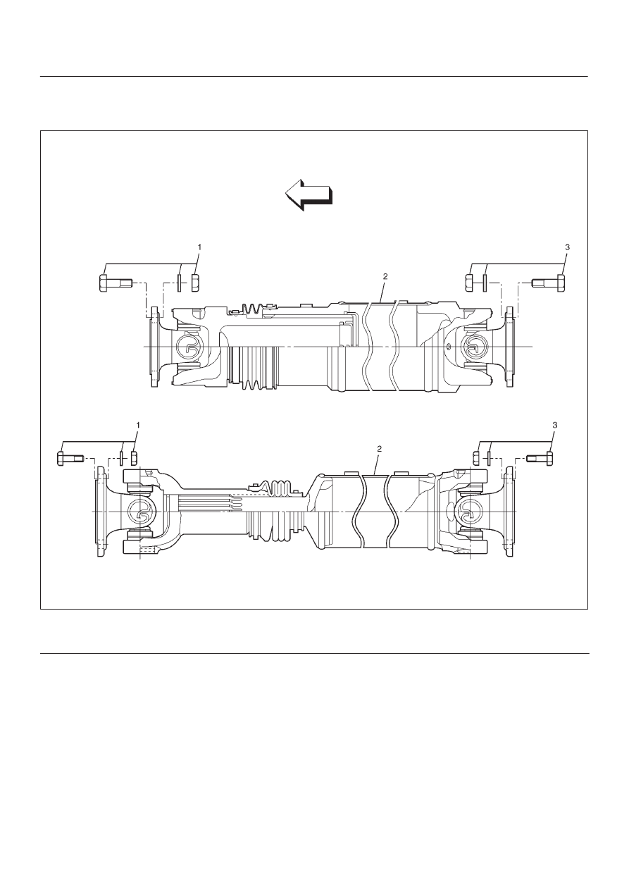
Rear Propeller Shaft and Associated Parts

401R200002

Legend

(1) Bolt, Nut and Washer (Transfer Side)

(2) Rear Propeller Shaft
(3) Bolt, Nut and Washer (Rear Axle Side)

Removal

1. Raise the vehicle on a hoist.

NOTE: Apply alignment marks on the flange at the rear
propeller shaft both front and rear side.

2. Remove transfer side bolt, nut and washer (except

spline yoke type).

3. Remove rear axle side bolt, nut and washer.
4. Remove rear propeller shaft.

NOTE: Plug the hole of the transmission rear end to
prevent oil leakage (spline yoke type only).

Installation

NOTE: Never install the shaft assembly backwards.
Never insert bar between yoke lugs when tightening or re-
moving bolts.
Completely remove the dust or foreign matter from the
connecting surface of flange coupling on each end of the
propeller shaft.

1. Align the mark which is applied at removal.
2. Install rear propeller shaft and tighten the bolts to the

specified torque.

Torque: 63 N·m(46 lb ft)

4C–37

DRIVE SHAFT SYSTEM

Slip Joint Disassembly

401RX00001

Legend

(1) Spline Yoke and Universal Joint Assembly
(2) Clamp

(3) Boot
(4) Clamp
(5) Tube and Universal Joint Assembly

1. Lay the shaft horizontally on a bench and secure.
2. Indicate the original assembled position by marking

the phasing of the shaft prior to disassembly.

3. Using the flat blade of a screwdriver, pry the loose end

of the boot clamp upwards and away from the
propeller shaft boot. Be careful not to damage the
boot.

4. When boot clamps becomes loose, remove by hand.
5. Repeat for the other boot clamp.
6. Remove the slip yoke assembly from the driveshaft,

by securing the boot with one hand and pulling on the
slip yoke.

7. Remove the boot from the shaft assembly.

4C–38

DRIVE SHAFT SYSTEM

Universal Joint Disassembly

401RX00007

Legend

(1) Spline Yoke
(2) Spider
(3) Propeller Shaft Assembly
(4) Spider

(5) Flange Yoke
(6) Bearing
(7) Snap Ring
(8) Flange Yoke

NOTE: Aluminum is softer than steel.  Care must be
taken not to remove excessive material or damage
bearing holes.
If the vehicle has aluminum tube type propeller shaft,
flange yoke, boot kit, journal kit can be replaced. If other
parts are damaged, replace propeller shaft assembly.

4C–39

DRIVE SHAFT SYSTEM

1. Apply alignment marks on the yokes of the universal

joint, then remove the snap ring.

401RW024

If the snap ring is stuck in position, remove paint from
the hole in the yoke or tap around the edge of the
bearing lightly with a soft drift.

401RW025

2. Set the yoke in the arbor press with a piece of tube

stock beneath it.
Place a solid plug on the upper bearing and press it
through to release the lower bearing.

401RW027

3. If the bearing will not pull out by hand after pressing,

tap the base of the lug near the bearing to dislodge it.

4. To remove the opposite bearing, turn the yoke over

and straighten the spider in the open spider hole.
Then carefully press on the end of the spider so the
remaining bearing moves straight out of the bearing
spider hole.  If the spider or bearing are cocked, the
bearing will score the walls of the spider hole and ruin
it.

401RW026


Content   ..  132  133  134  135   ..