Isuzu Amigo / Axiom / Trooper / Rodeo / VehiCross. Manual - part 1319


  Index      Isuzu     Isuzu Amigo / Axiom / Trooper / Rodeo / VehiCross - service repair manual 1999-2002 year


Search            


Content   ..  1317  1318  1319  1320   ..


Isuzu Amigo / Axiom / Trooper / Rodeo / VehiCross. Manual - part 1319


6E1–352

RODEO Y22SE 2.2L ENGINE DRIVEABILITY AND EMISSION

DIAGNOSTIC TROUBLE CODE (DTC) 

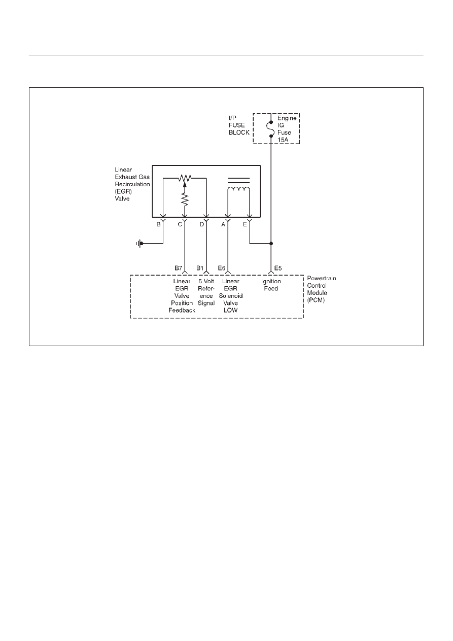
P1404 EXHAUST GAS RECIRCULATION (EGR) CLOSED VALVE

060R100039

Circuit Description

The powertrain control module (PCM) monitors the
exhaust gas recirculation(EGR) valve pintle position input
to ensure that the valve responds properly to commands
from the PCM to detect a fault if the pintle position sensor
and control circuits are open or shorted. If the PCM
detects a pintle position signal voltage below the normal
range of the pintle position sensor, or a signal voltage that
is not within a tolerance considered acceptable for proper
EGR control system operation, the PCM will set a DTC
P1404.

Conditions for Setting the DTC

D

IAT is above 5

°

C (41

°

)

D

EGR actual position is 16 counts below the EGR low
threshold for 3 iterations per 5 seconds.

Action Taken When the DTC Sets

D

The PCM will illuminate the Malfunction Indicator Lamp
(MIL) after the second consecutive trip in which the
fault is detected.

D

The PCM will store conditions which were present
when the DTC was set as Freeze Frame and in the
Failure Records data.

Conditions for Clearing the MIL/DTC

D

The PCM will turn the MIL OFF on the third consecutive
trip cycle during which the diagnostic has been run and
the fault condition is no longer present.

D

A history DTC P1404 will clear after 40 consecutive
warm up cylcles without a fault.

D

DTC P1404 can be cleared by using the Scan Tool’s
”Clear Info” function.

Diagnostic Aids

Check for the following conditions:

D

Excessive deposits on EGR valve pintle or seat –
Check for deposits that may interfere with the EGR
valve pintle extending completely or cause the pintle to
stick.

D

Poor connection or damaged harness – Inspect the
wiring harness for damage. If the harness appears to
be OK, observe the EGR actual position display on the
Tech 2 while moving connectors and wiring harnesses
related to the EGR valve. A change in the display will
indicate the location of the fault.

Reviewing the Failure Records vehicle mileage since the
diagnostic test last failed may help determine how often
the condition that caused the DTC to be set occurs. This
may assist in diagnosing the condition.

NOTE: If the EGR valve show signs of excessive heat,
check the exhaust system for blockage (possible a
plugged catalytic converter) using the ”Restricted
Exhaust System Check”.

6E1–353

RODEO Y22SE 2.2L ENGINE DRIVEABILITY AND EMISSION

DTC P1404 EGR Closed Valve


Step

Action

Value(s)

Yes

No

1

Was the ”On–Board Diagnostic (OBD) System Check
performed?

Go to Step 2 

Go to OBD

System

Check 

2

1. Turn the ignition switch ON, with the engine OFF.
2. Review and record the Tech 2 Failure Records data,

the clear the DTCs.

3. Operate the vehicle within the Failure Records

conditions noted.

4. Using the Tech 2, monitor ”DTC” info for DTC

P1404.

Does the Tech 2 indicate DTC P1404 ”Ran and
Passed”

Refer to

Diagnostic

Aids 

Go to Step 3 

3

1. Ignition OFF.
2. Disconnect the Linear Exhaust Gas Recirculation

(EGR) Valve from the wiring harness.

3. Ignition ON, Engine OFF.
4. Using a Digital Voltmeter (DVM), check for voltage

on the Ignition feed circuit at the Linear Exhaust Gas
Recirculation (EGR) Valve wiring harness
connector.

Does the DVM read the following value?

12 volts

Go to Step 6 

Go to Step 4 

4

Check the Ignition feed circuit, between the EGR
sensor and the ”Engine IG.” fuse, for the following
conditions:

D

An Open circuit

D

A short to ground

Was the problem found?

Verify repair

5

Using a DVM, check the resistance of the EGR
solenoid.

Does the DVM read the following value?

less than 5 

W

Go to Step 6 

Go to Step 14

6

Check the EGR solenoid valve Low circuit, between the
EGR sensor and the PCM, for the following conditions:

D

An Open circuit

D

A short to ground

Was the problem found?

Verify repair

Go to Step 15

7

1. Ignition OFF.
2. Disconnect the Linear Exhaust Gas Recirculation

(EGR) Valve from the wiring harness.

3. Ignition ON, Engine OFF.
4. Observe the EGR value on the Tech 2.

Does the Tech 2 display the following value(s)?

0 volts 0%

Go to Step 9 

Go to Step 8 

8

Check the EGR position feedback circuit, between the
EGR sensor and the PCM, for the following conditions:

D

An Open circuit

D

A short to ground

Was the problem found?

Verify repair

Go to Step 15

6E1–354

RODEO Y22SE 2.2L ENGINE DRIVEABILITY AND EMISSION

DTC P1404 EGR Closed Valve

  (Cont'd)

Step

No

Yes

Value(s)

Action

9

1. Ignition ON, engine OFF.
2. Using a Digital Voltmeter (DVM), check for voltage

on the 5 volt Reference signal circuit at the Linear
Exhaust Gas Recirculation (EGR) Valve wiring
harness connector.

Does the DVM read the following value?

about 5 volts

Go to Step 11

Go to Step 10

10

Check the 5 volt reference signal circuit, between the
EGR and the PCM, for the following conditions:

D

An Open circuit

D

A short to ground

Was the problem found?

Verify repair

Go to Step 11

11

1. Ignition OFF.
2. Place a DVM between the 5 volt reference signal

circuit and the 5 volt signal return (ground) circuit at
the EGR wiring harness connector.

3. Ignition ON, Engine OFF.

Does the DVM read the following value?

about 5 volts

Go to Step 13

Go to Step 12

12

Check the 5 volt signal return (ground) circuit, between
the EGR and the PCM, for the following conditions:

D

An Open circuit

D

A short to ground

Was the problem found?

Verify repair

Go to Step 15

13

1. Ignition OFF.
2. Place a fused jumper wire between the 5 volt

reference signal circuit and the EGR valve position
feedback circuit at the EGR wiring harness
connector.

3. Ignition ON, Engine OFF.
4. Observe the EGR value on the Tech 2.

Does the Tech 2 display the following value?

5 volts 100%

Go to Step 14

Go to Step 15

14

Replace the Linear Exhaust Gas Recirculation (EGR)
Value.
Verify repair.

15

Replace the PCM.

IMPORTANT: The replacement PCM must be
programmed. Refer to On–Vehicle Service in
Powertrain Control Module and Sensors for
procedures.

And also refer to latest Service Bulletin.
Check to see if the Latest software is released or not.
And then Down Load the LATEST PROGRAMMED
SOFTWARE to the replacement PCM.

Verify repair.

6E1–355

RODEO Y22SE 2.2L ENGINE DRIVEABILITY AND EMISSION

DIAGNOSTIC TROUBLE CODE (DTC) P1441 EVAPORATIVE EMISSION (EVAP)

SYSTEM FLOW DURING NON–PURGE

060R100040

Circuit Description

Canister purge is controlled by a solenoid valve that
allows manifold vacuum to purge the canister. The
powertrain control module (PCM) supplies a ground to
energize the solenoid valve (purge ON). The EVAP purge
solenoid control is pulse–width modulated (PWM) and is
turned ON and OFF several times a second. The duty
cycle (pulse width) is determined by engine operating
conditions including load, throttle position, coolant
temperature and ambient temperature. The duty cycle is
calculated by the PCM and the output is commanded
when the appropriate conditions have been met.
The EVAP purge vacuum switch is a normally closed
switch positioned in the purge line between the canister
and the EVAP purge solenoid. The EVAP purge vacuum
switch will open when vacuum increases to greater than 5
inches of water pressure in the purge line. The PCM
monitors the EVAP purge vacuum switch signal to
determine if the evaporative emission control system is
working properly. If the switch is open (purge flow
detected) when the PCM is not commanding the EVAP
purge solenoid ON, DTC P1441 will be set.  DTC P1441 is
a type A code.

Conditions for Setting the DTC

D

No active system voltage, ECT sensor, IAT sensor, VS
sensor, MAP sensor, vacuum switch, or TP sensor,
EGR, EVAP DTCs set.

D

BARO reading is above 72.3 kPa.

D

Start–up intake air temperature (IAT) and start–up
engine coolant temperature(ECT) are both between
4.2

°

C (40

°

F) and 35

°

C (95

°

F).

D

The difference between start–up ECT and start–up IAT
is less than 6.75

°

C(12.2

°

F).

D

The Fuel Tank Level Sensor reads between 15% and
85%.

D

Fuel thank vacuum is greater than 5 cm (2 inches) of
water for 2 seconds.

Action Taken When the DTC Sets

D

The PCM will illuminate the malfunction indicator lamp
(MIL) after the second consecutive trip in which the
fault is detected.

D

The PCM will store conditions which were present
when the DTC was set as Freeze Frame and in the
Failure Records data.

Conditions for Clearing the MIL/DTC

D

The PCM will turn the MIL OFF on the third consecutive
trip cycle during which the diagnostic has been run and
the fault condition is no longer present.

D

A history DTC P1441 will clear after 40 consecutive
warm–up cycles have occurred without a fault.

D

DTC P1441 can be cleared by using the Scan Tool’s
”Clear Info” function.


Content   ..  1317  1318  1319  1320   ..