Content .. 1251 1252 1253 1254 ..
Isuzu Amigo / Axiom / Trooper / Rodeo / VehiCross. Manual - part 1253
6E1–88
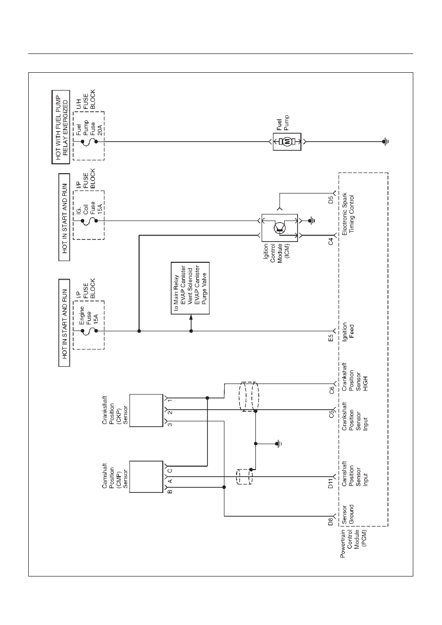
RODEO Y22SE 2.2L ENGINE DRIVEABILITY AND EMISSION
ENGINE CRANKS BUT WILL NOT RUN
060R100005
Index Isuzu Isuzu Amigo / Axiom / Trooper / Rodeo / VehiCross - service repair manual 1999-2002 year
|
|
|
Content .. 1251 1252 1253 1254 ..
6E1–88 RODEO Y22SE 2.2L ENGINE DRIVEABILITY AND EMISSION ENGINE CRANKS BUT WILL NOT RUN 060R100005 |