Isuzu Amigo / Axiom / Trooper / Rodeo / VehiCross. Manual - part 1216


  Index      Isuzu     Isuzu Amigo / Axiom / Trooper / Rodeo / VehiCross - service repair manual 1999-2002 year


Search            


Content   ..  1214  1215  1216  1217   ..


Isuzu Amigo / Axiom / Trooper / Rodeo / VehiCross. Manual - part 1216


6A–61

ENGINE MECHANICAL (Y22SE 2.2L)

Inspection and Repair

1. Inspect the cylinder head gasket and any other

material adhering to the upper surface of the cylinder
block. 

CAUTION: Be very careful not to allow any material
to accidentally drop into the cylinder block. Be very
careful not to scratch the cylinder block.

2. Carefully inspect the oil pump, rear oil seal retainer,

and crankcase assembly installation surface seal.

3. Wipe the cylinder block clean.
4. Visually inspect the cylinder block. If necessary, use a

flaw detector to perform a dye penetrate and
hydraulic (or air pressure) test. If cracking or other
damage is discovered, the cylinder block must either
be repaired or replaced.
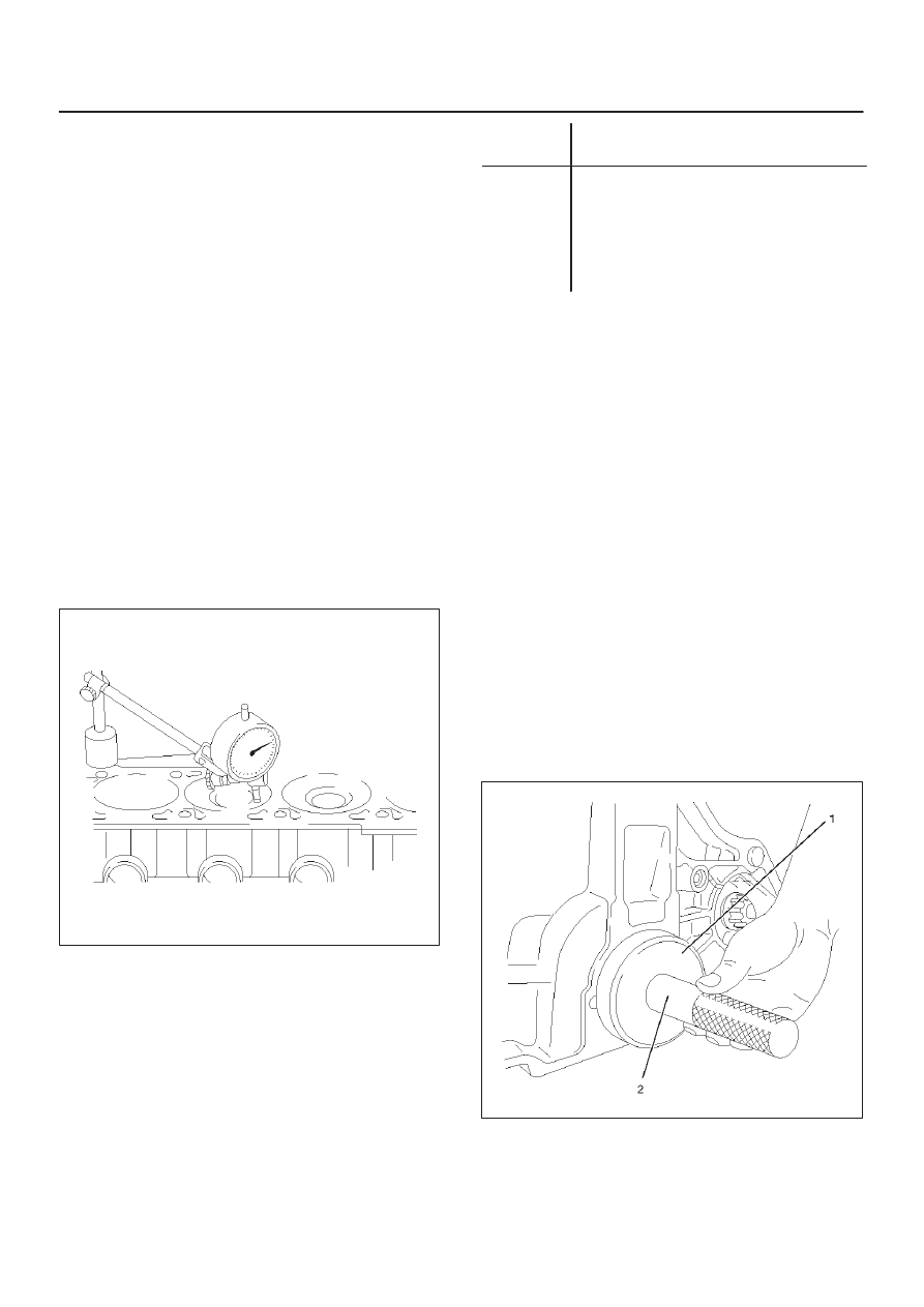
Flatness

1. Using a straight edge and feeler gauge, check that the

upper surface of the cylinder block is not warped.

CAUTION: Be very careful not to allow any material
to accidentally drop into the upper surface of the
cylinder block. Be very careful not to scratch the
upper surface of the cylinder block.

2. After re-grinding cylinder block maximum piston

protrusion 0.4 mm (0.0157 in).

012RW013

Cylinder Bore

Use a cylinder gauge to measure the cylinder bore
diameter in both the axial and thrust directions. Each
measurement should be made at six points.

CAUTION: Be very careful not to allow any material
to accidentally drop into the upper surface of the
cylinder block. Be very careful not to scratch the
upper surface of the cylinder block.
If the measurement exceeds the specified limit, the
cylinder block must be replaced.

Grade
number

Cylinder bore

99

85.985 – 85.995 mm

(3.3852 – 3.3856 in)

00

85.995 – 86.005 mm

(3.3856 – 3.3860 in)

O/S 0.5

86.495 – 86.505 mm

(3.4053 – 3.4057 in)

NOTE: For information on piston diameter, please refer
to the section “Inspection and repair of the Piston and
Connecting Rod” in this manual.

Reassembly

1. Cylinder block.
2. Install crankshaft.

D

Install the main bearings to the cylinder block and
the main bearing caps.

Apply liquid gasket to rear bearing cap in slots
provided.

D

Be sure that they are positioned correctly.

D

Apply new engine oil to the upper and lower main
bearing faces.

NOTE: Do not apply engine oil to the bearing back faces.

D

Carefully mount the crankshaft.

D

Apply engine oil to the thrust washer.

3. Install rear oil seal.

D

Coat lip of seal rings thinly with protective grease.

D

Install seal ring into cylinder block, use J–42616 (1)
and J–42613 (2).

015RW009

Refer to “Crankshaft” in this manual.

6A–62

ENGINE MECHANICAL (Y22SE 2.2L)

4. Install flywheel

1. Thoroughly clean and remove the oil from the

threads of crankshaft.

2. Remove the oil from the crankshaft and flywheel

mounting faces.

3. Mount the flywheel on the crankshaft then install

the washer and temporally hand tighten bolts.

4. Use stopper (J–42618) to prevent the crankshaft

from rotating.
Tighten the flywheel bolts in 2 steps:

1st step: 65 N·m (48 lb ft)

2nd step: 30

°

 – 45

°

NOTE: Do not reuse the bolt.

015RW010

5. Install piston and connecting rod assembly.

D

Apply engine oil to the cylinder bores, the
connecting rod bearings and the crankshaft pins.

NOTE: Do not apply engine oil to the bearing back faces.

D

Position ring gaps:

1 — Compression rings 180

°

 to each other as

illustrated (A).
2 — Offset oil control rings 25 to 50 mm (1 to 2 in)
from gap of second compression ring (B).

015R100025

Refer to “Piston and Connecting Rod” in this manual.

6. Install balance unit assembly and tighten the bolts.

Torque : 30 N·m (22 lb ft)

7. Install oil pump assembly, refer to section 6G “Oil

Pump” in this manual.

8. Install oil strainer.
9. Install oil pan support.

10. Install oil pan assembly.

Refer to “Crankshaft” in this manual.

6A–63

ENGINE MECHANICAL (Y22SE 2.2L)

Balance Unit Assembly

Balance Unit Assembly and Associated Parts

051R100007

Legend

(1) Oil Pan
(2) Oil Pan Support

(3) Oil Strainer
(4) Balance Unit Assembly
(5) Shim

Disassembly

1. Remove the oil pan.
2. Remove the oil pan support.

6A–64

ENGINE MECHANICAL (Y22SE 2.2L)

3. Remove the oil strainer (1) from oil pump and the oil

baffle plate (2).

051RW009

Adjustment

1. Turn crankshaft in engine rotational direction to align

the alignment mark (2) at 1st cylinder “TDC”.

014RW066

2. In this crankshaft position, the flattened side (arrows)

of both balancer shafts must face downward and
must be on a horizontal line.

051RW010

3. Screw measuring device J–43038 (3) with long

knurled bolt (1) into 1st balancer shaft (intake side)
and tighter hand–tight measuring arm (5) must point
in “9 o’clock” direction shown in this illustration.
Install dial gauge holder with dial gauge (4) on
cylinder block.

051RW007


Content   ..  1214  1215  1216  1217   ..