Isuzu Amigo / Axiom / Trooper / Rodeo / VehiCross. Manual - part 1209


  Index      Isuzu     Isuzu Amigo / Axiom / Trooper / Rodeo / VehiCross - service repair manual 1999-2002 year


Search            


Content   ..  1207  1208  1209  1210   ..


Isuzu Amigo / Axiom / Trooper / Rodeo / VehiCross. Manual - part 1209


6A–33

ENGINE MECHANICAL (Y22SE 2.2L)

Rotate camshaft 720

°

 clockwise only until timing

marks align.
If accidentally rotated too far, not turn anti
clockwise, this will result in incorrect tensioner
setting

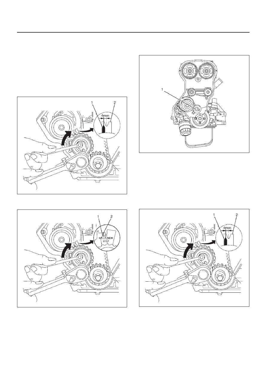
c. Slightly loosen the fastening bolt of the timing belt

tension roller, depending on the version, rotate the
adjustment cam in direction of arrow (clockwise)
until:
Version 1: Pointer (1) of the timing belt tension
roller is approx. 4 mm to the left of the notch (2).

014R100008

d. Version 2: Pointer (1) of the timing belt tension

roller aligns with the “USED” notch (2).

014R100009

e. Tighten the fastening bolt (1) of the timing tension

roller.

Torque: 25 N·m (18 lb ft)

020RW010

f. Remove the fixing tool J–43037.
g. Turn the crankshaft another two turns (720

°

) in

engine rotational direction to mark 1st cylinder
TDC and check adjustment of the timing belt
tension roller. Ensure crankshaft is only turned
clockwise, do not turn back, this will result in
incorrect tensioner setting. If the pointer (1) of the
timing belt tension roller does not align with the
corresponding mark (2), the adjustment procedure
must be repeated.

014R100008

6A–34

ENGINE MECHANICAL (Y22SE 2.2L)

014R100009

4. Install timing belt front cover and tighten two bolts to

the specified torque.

Torque: 6 N·m (52 lb in)

5. Install engine harness cover to front top of engine and

tighten nut to the specified torque.

Torque: 6 N·m (52 lb in)

6. Install crankshaft pulley and tighten four bolts.

Torque: 20 N·m (14 lb ft)

020RW014

7. Move drive belt tensioner to loose side using wrench

then install drive belt to normal position.

033RW001

8. Connect engine harness three connector to chassis

harness of left rear side of engine compartment.

9. Connect battery ground cable.

6A–35

ENGINE MECHANICAL (Y22SE 2.2L)

Camshaft

Camshaft and Associated Parts

011R100005

Legend

(1) Camshaft Pulley Fixing Bolt
(2) Camshaft Pulley
(3) Oil Seal

(4) Camshaft Bracket
(5) Camshaft Bracket Fixing Bolt
(6) Camshaft Assembly Exhaust
(7) Camshaft Assembly Intake

Removal

1. Disconnect battery ground cable.
2. Remove cylinder head cover.

Refer to removal procedure for Cylinder Head Cover
in this manual.

3. Remove timing belt tensioner and remove timing belt.

020RW010

6A–36

ENGINE MECHANICAL (Y22SE 2.2L)

4. Use adjustable wrench to hexagonal portion of

camshaft, and remove fixing bolt for camshaft pulley
from front end of camshaft.

014RW074

5. Remove camshaft drive pulley from intake and

exhaust camshaft.

6. Remove twenty fixing bolts from intake and exhaust

camshaft bracket on the cylinder head, then remove
camshafts.

011RW015

CAUTION:

D

Do not damage camshaft lobe and journal.

D

Do not damage hydraulic lash adjuster(HLA) and
do not allow into foreign materials into cylinder
head.

7. Remove oil seal from camshaft.

Installation

1. Clean surface of camshaft bracket and HLA.
2. Apply engine oil to journal surface of camshaft

bracket and HLA.

3. Install camshaft to cylinder head.
4. Install camshaft bracket according to numerical as

shown in the illustration.
The bracket number is:

D

Exhaust: 1 to 5 from front 

D

Intake: 6 to 10 from front.

014RW052

Camshaft oil seal installation area on the cylinder
head of No.1, No.6 and camshaft bracket rear side
plug portion must be applied HN1023 or equivalent as
in the illustration.

014R100004


Content   ..  1207  1208  1209  1210   ..