Isuzu Amigo / Axiom / Trooper / Rodeo / VehiCross. Manual - part 1206


  Index      Isuzu     Isuzu Amigo / Axiom / Trooper / Rodeo / VehiCross - service repair manual 1999-2002 year


Search            


Content   ..  1204  1205  1206  1207   ..


Isuzu Amigo / Axiom / Trooper / Rodeo / VehiCross. Manual - part 1206


6A–21

ENGINE MECHANICAL (Y22SE 2.2L)

Intake Manifold

Removal

1. Disconnect battery ground cable.
2. Remove PCV hose from air intake duct.
3. Remove a nut from air intake duct bracket and loosen

hose clamp on throttle body. Remove air intake duct
assembly with air cleaner cover.

4. Drain engine coolant.
5. Remove water hoses from throttle body.
6. Disconnect the connector for throttle position sensor,

idle air control valve sensor from throttle body.

7. Remove fuel pipe joint eye bolts from fuel rail and

disconnect wire harness from fuel injector.

042RW001

8. Disconnect hose from fuel pressure regulator then

remove fuel rail assembly.

9. Remove throttle valve control cable from throttle

body.

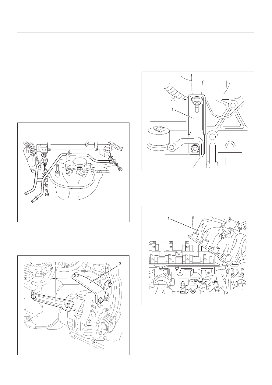
10. Remove fixing bolts for generator bracket.

065RW025

11. Remove water pipe fixing bolt then remove water

pipe.

12. Remove fixing bolt from bracket (Between cylinder

block and intake manifold) of intake manifold side.

025RW002

13. Remove ignition coil bracket fixing bolt.
14. Remove the brake booster vacuum hose.
15. Remove the four throttle body nuts.
16. Remove bolt and seven nuts, and remove intake

manifold.

027RW002

6A–22

ENGINE MECHANICAL (Y22SE 2.2L)

Installation

1. Install intake manifold with gasket to cylinder head,

tighten bolt and nuts to the specified torque.

Torque: 22 N·m (16 lb ft)

NOTE: Do not re-use the bolts and nuts.

027RW002

2. Install ignition coil bracket fixing bolt.

Torque: 20 N·m (14 lb ft)

3. Install intake manifold bracket, tighten bolt.

Torque: 25 N·m (18 lb ft)

025RW002

4. Install water pipe to intake manifold.
5. Install the throttle body with paper gasket to the intake

manifold, tighten the four nuts.

Torque: 9 N·m (78 lb in)

6. Install generator bracket and tighten generator

bracket bolts.

Torque
Long bolts: 35 N·m (25 lb ft)
Short bolts: 20 N·m (14 lb ft)

065RW025

7. Install fuel rail assembly to intake manifold and

connect hose between fuel pressure regulator and
throttle body.

8. Install fuel pipe and tighten joint eye bolt and connect

fuel injector harness.

Torque: 25 N·m (18 lb ft)

042RW001

6A–23

ENGINE MECHANICAL (Y22SE 2.2L)

9. Connect the connector for throttle position sensor

and idle air control valve sensor to throttle body.

10. Install water hoses to throttle body.

11. Install intake duct assembly to throttle body and air

cleaner then tighten nut to the intake duct bracket and
clamp on the throttle body side and air cleaner side.

Torque: 7 N·m (61 lb in)

12. Install PCV hose to air intake duct.
13. Install throttle valve control cable to throttle body.
14. Confirm the free play of throttle valve control cable.

Free play: 5.7 to 6.3 mm

15. Fill engine coolant to full level from radiator filler neck.
16. Connect battery ground cable.

6A–24

ENGINE MECHANICAL (Y22SE 2.2L)

Cylinder Head Assembly

Removal

1. Disconnect battery ground cable.
2. Disconnect connector of intake air temperature

sensor from intake air duct.

3. Remove PCV hose from air intake duct.
4. Remove nut from air intake duct bracket and loosen

hose clamp on throttle body. Remove air intake duct
assembly with air cleaner cover.

5. Remove intake air duct bracket from cylinder head.
6. Drain engine coolant.
7. Move drive belt tensioner to loose side using wrench

then remove drive belt.

033RW001

8. Remove radiator upper hose from engine side.
9. Remove four nuts of exhaust front pipe.

10. Remove three bolts from generator bracket then

remove the generator with brackets.

065RW025

11. Disconnect crankshaft angle sensor connector.

12. Disconnect knock sensor connector.

13. Remove heater hose from adapter side.
14. Remove heater hose from water pipe side.
15. Remove water hose between water pipe and throttle

body.

16. Remove fuel pipe joint eye bolts from fuel rail

assembly and remove fuel pipe bracket with electric
ground cable.

042RW001

17. Disconnect connector for evaporation valve.
18. Remove canister hose.
19. Remove fixing nut of intake manifold stay from

cylinder block side.

025RW002

20. Remove two bolts from intake manifold for water pipe

support and remove cylinder head assembly.

21. Remove engine harness cover and disconnect three

connectors from chassis harness on left rear side
engine compartment.

22. Disconnect connector for power steering pump

pressure switch.


Content   ..  1204  1205  1206  1207   ..