Isuzu Amigo / Axiom / Trooper / Rodeo / VehiCross. Manual - part 1199


  Index      Isuzu     Isuzu Amigo / Axiom / Trooper / Rodeo / VehiCross - service repair manual 1999-2002 year


Search            


Content   ..  1197  1198  1199  1200   ..


Isuzu Amigo / Axiom / Trooper / Rodeo / VehiCross. Manual - part 1199


PARKING BRAKE SYSTEM (4x4 Model)

5D1–5

Removal

1. Remove rear wheels (1).

2. Remove 2 bolts to remove the caliper assembly (2)

from the support bracket. Refer to Rear Disc Brakes
in Power Assisted Brake System section.
Temporarily hang the caliper with wire etc.

3. Remove rotor (drum) (3).

4. Remove holding spring (4), upper return spring (5)

and lower return spring (6).

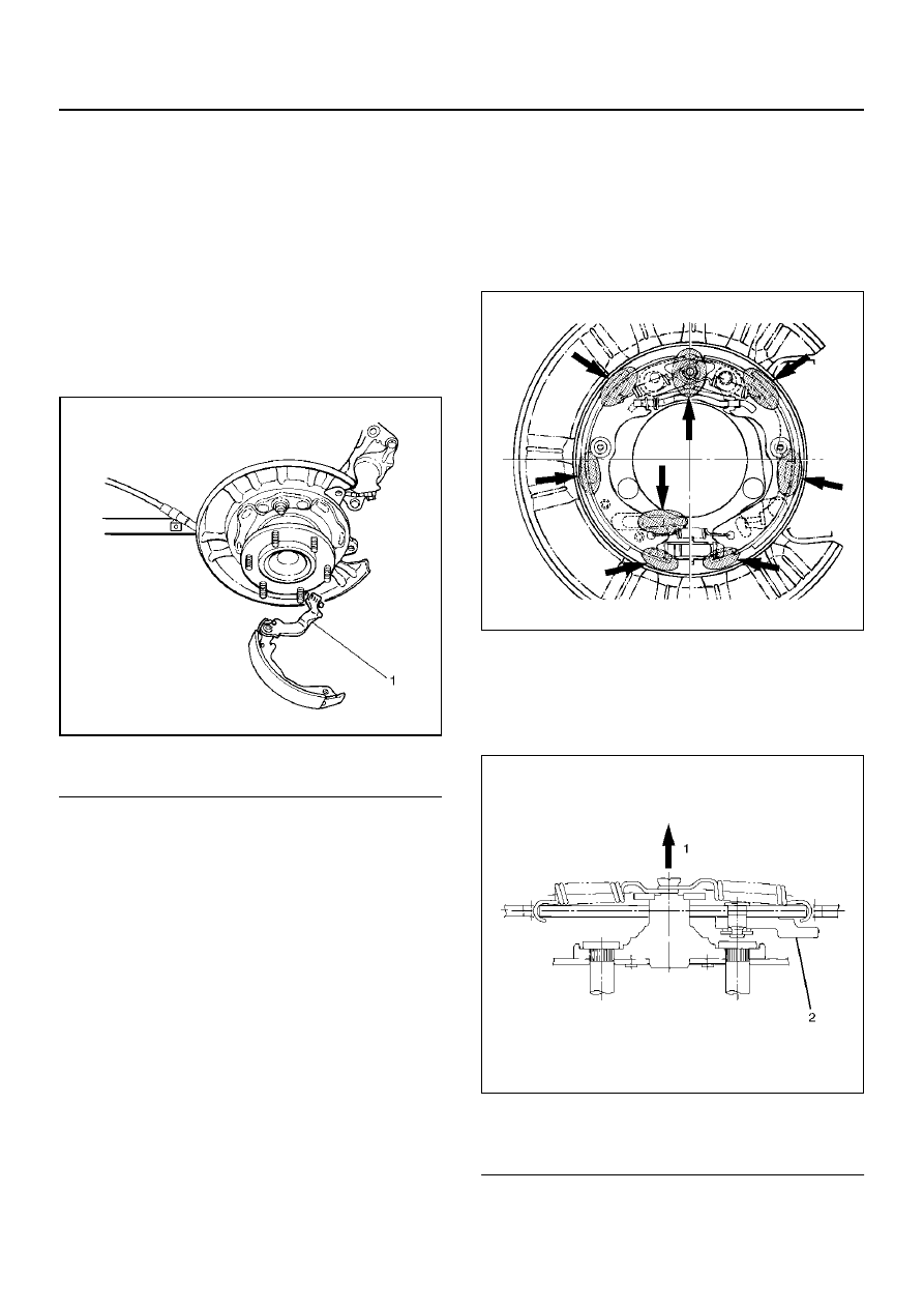
5. Previously remove the rear cable from the parking

brake lever, then remove the brake shoe assembly
(7).

308RW004

EndOFCallout

6. Remove cable fixing bolt (8) and bolt (9) (10) (11).

7. Remove nut (12).

8. Remove nut (13) and retainer (14).

9. Remove rear cable (15).

Installation

1. Apply grease (BESCO L–2 or equivalent) to the

connecting portion of the rear cable and equalizer.
Install rear cable (15).

2. Install retainer (14).

• Tighten nut (13) to the specified torque.

Torque: 41N·m (30lb ft)

3. Tighten nut (12) to the specified torque. 

Torque: 15N·m (11lb ft)

4. Tighten bolt (11) (10) (9) to the specified torque.

Torque: 6.5N·m (57lb in)

• To adjust the parking brake, refer to Parking

Brake Adjustment in this section.

5. Tighten the cable fixing bolt (8) to the specified

Torque: 6.5N·m (57lb in)

6. Install shoe assembly (7).

After installation of the shoe and cable assembly,
apply special grease (included in the repair kit) to
the following portions indicated in the figure.

308RS005

7. Install lower return spring (6) and upper return

spring (5).
The parking brake lever side (secondary side) return
spring must be installed on the outer side of the
primary side return spring.

308RS003

EndOFCallout

8. Install holding spring (4).

9. Install rotor (drum) (3).

Legend

(1) Parking Brake Lever

Legend

(1) Outer Side
(2) Parking Lever

5D1–6

PARKING BRAKE SYSTEM (4x4 Model)

10. Install caliper assembly (2).

11. Install rear wheels (1).

Inspection and Repair

Parking Brake Lining Inspection

Check the shoe assemblies for wear by removing the
brake drum. 
Replace the shoe assemblies if the lining thickness is
less than 1.0 mm (0.039 in).

Minimum limit: 1.0m (0.039in)

308RS004

Parking Brake Rotor (Drum) Inspection

Refer to Rear Disc Brakes in Power-Assisted Brake
System section for inspection procedure of the rotor
(drum).

Parking Brake Adjustment

1. Prior to lever stroke adjustment, adjust rear brake

shoe/rotor (drum) gap. Perform this procedure with
loosening the adjust nut of the hand brake lever.

2. Remove the adjusting hole plug (rubber) and turn

the shoe adjusting screw downward with a small
screwdriver so that shoes will expand until they get
into close touch with the rotor. (Turn down the
adjusting screw notch by notch until the rotor does
not turn.)

3. Turn the adjusting screw in the opposite direction

(upward) until the rotor can be turned lightly.
Standard number of notches to turn upward: 7 or 8
Turn the rotor and make sure that there is no brake
dragging.

4. After the rear brake shoe/rotor (drum) gap has been

adjusted, perform parking brake cable adjustment.

5. Turn the adjusting nut so that the parking brake

lever travels 6–8 notches when pulled up with a

force of 30 kg (66 lb).

6. Make sure there is no brake dragging. Then tighten

the cable lock nut

Torque : 13 N·m (113 lb in)

7. When poor braking effect possibly resulting from

insufficient break–in is felt, or just after replacement
of parking brake shoe, be sure to conduct break–in
as follows:

8. Forward 50 km/h (30 mph) 

´ 400 m (About 30

seconds) with a lever pull force of 15 kg (33 lb).

9. Backward 10 km/h (6 mph) 

´ 50 m (About 18

seconds) with a lever pull force of 15 kg (33 lb).

NOTE:  Break–in procedures must be performed under
safe conditions and traffic rules.

• If braking effect still remains poor after the above

break–in, wait for some time until parking brake shoe
cools down and repeat the procedures 8. and 9.
noted above. 

• On completion of break–in, inspect parking brake

lever stroke, and if the lever does not come within the
specified number of notches when pulled up,
readjust.

• Excessive break–in may cause premature wear of

the parking brake lining.

PARKING BRAKE SYSTEM (4x4 Model)

5D1–7

Main Data and Specifications

General Specifications

Torque Specifications

311RY00005

Model

Type

Duo–servo

Drum inside diameter

210 mm(8.27 in)

Parking brake lever stroke

6–8 notches

When pulled with a force of 30 kg (66 lb)

PARKING BRAKE SYSTEM (4X2 Model)

5D2–1

RODEO

BRAKES

CONTENTS

PARKING BRAKE SYSTEM (4´2 Model)

Service Precaution. . . . . . . . . . . . . . . . . . . . .

5D2–1

General Description . . . . . . . . . . . . . . . . . . . .

5D2–1

Parking Brake Lever  . . . . . . . . . . . . . . . . . . .

5D2–2

Parking Brake Lever Assembly and

Associated Parts  . . . . . . . . . . . . . . . . . . . .

5D2–2

Removal . . . . . . . . . . . . . . . . . . . . . . . . . . .

5D2–2

Installation  . . . . . . . . . . . . . . . . . . . . . . . . .

5D2–2

Parking Brake Rear Cable . . . . . . . . . . . . . . .

5D2–3

Parking Brake Rear Cable and Associated

Parts . . . . . . . . . . . . . . . . . . . . . . . . . . . . . .

5D2–3

Removal . . . . . . . . . . . . . . . . . . . . . . . . . . .

5D2–4

Installation. . . . . . . . . . . . . . . . . . . . . . . . . .

5D2–4

Parking Brake Adjustment  . . . . . . . . . . . . .

5D2–4

Main Data and Specifications  . . . . . . . . . . . .

5D2–5

Service Precaution

WARNING:  THIS VEHICLE HAS A SUPPLEMENTAL
RESTRAINT SYSTEM (SRS). REFER TO THE 

SRS

COMPONENT AND WIRING LOCATION VIEW IN
ORDER TO DETERMINE WHETHER YOU ARE
PERFORMING SERVICE ON OR NEAR THE SRS
COMPONENTS OR THE SRS WIRING. WHEN   YOU
ARE PERFORMING SERVICE ON OR NEAR THE
SRS COMPONENTS OR THE SRS WIRING, REFER
TO THE 

SRS SERVICE INFORMATION. FAILURE TO

FOLLOW WARNINGS COULD RESULT IN POSSIBLE
AIR BAG DEPLOYMENT, PERSONAL INJURY, OR
OTHERWISE UNNEEDED SRS SYSTEM REPAIRS.

CAUTION:  Always use the correct fastener in the
proper location. When you replace a fastener, use
ONLY the exact part number for that   application.
ISUZU will call out those fasteners that require a
replacement after removal. ISUZU will also call out
the fasteners that require   thread lockers or thread
sealant. UNLESS OTHERWISE SPECIFIED, do not
use supplemental coatings (Paints, greases, or
other corrosion   inhibitors) on threaded fasteners
or fastener joint interfaces. Generally, such
coatings adversely affect the fastener torque and
the joint   clamping force, and may damage the
fastener. When you install fasteners, use the correct
tightening sequence and specifications.   Following
these instructions can help you avoid damage to
parts and systems.

General Description

Pulling up the parking brake lever by hand will set the
parking brake. By means of a ratchet type lock, the lever
can be held in that position until it is released. The
position of the lever is transmitted through cable/lever
systems to the rear wheels. These parts are designed to
obtain sufficient braking force even when parking on
slopes. When the parking brake is set, or when the
ignition SW is in the“ON” position, the brake warning
light illuminates. The rear wheel parking brake is a
leading/trailing brake (mechanical inside expansion
type). Parking brake adjustment is made through the
adjusting hole (bored through back plate). Parking
brake lever stroke should be adjusted to 6 notches.
Refer to Parking Brake Adjustment in this section.

SECTION


Content   ..  1197  1198  1199  1200   ..