Content .. 1190 1191 1192 1193 ..
Isuzu Amigo / Axiom / Trooper / Rodeo / VehiCross. Manual - part 1192
POWER-ASSISTED BRAKE SYSTEM
5C–35
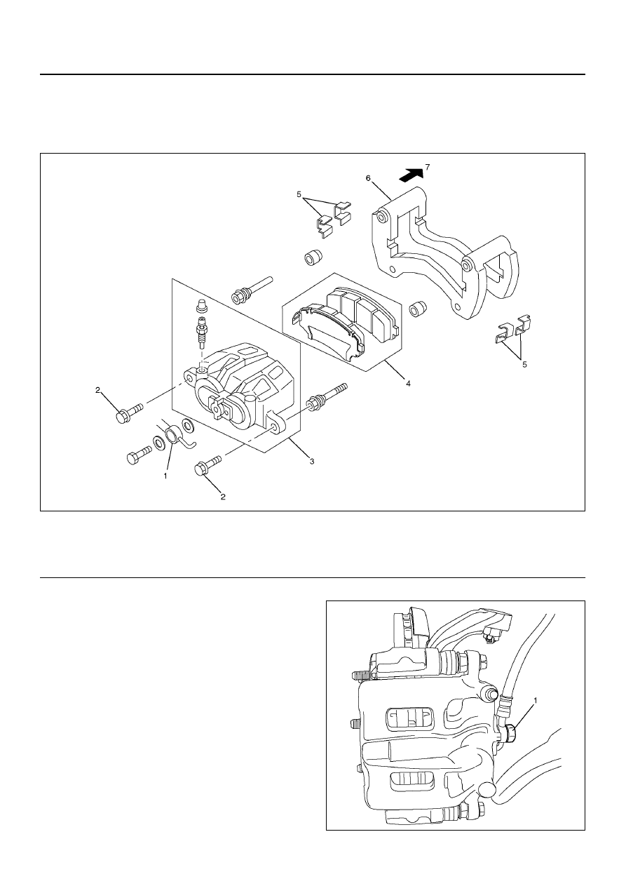
Front Disc Brake Caliper Assembly
Front Disc Brake Caliper Assembly
and Associated Parts
302R200027
EndOFCallout
Removal
1. Raise the vehicle and support with suitable safety
stands.
2. Remove wheel and tire assembly, refer to Wheels
and Tires System in Section 3E.
3. Remove the bolt and gaskets, then disconnect the
flexible hose from the caliper and after
disconnecting the flexible hose (1), cap or tape the
openings to prevent entry of foreign material.
302R200007
Legend
(1) Brake Flexible Hose
(2) Pin Bolt
(3) Caliper Assembly
(4) Pad Assembly
(5) Clip
(6) Support Bracket with Pad Assembly
(7) Outer Side