Content .. 1185 1186 1187 1188 ..
Isuzu Amigo / Axiom / Trooper / Rodeo / VehiCross. Manual - part 1187
POWER-ASSISTED BRAKE SYSTEM
5C–15
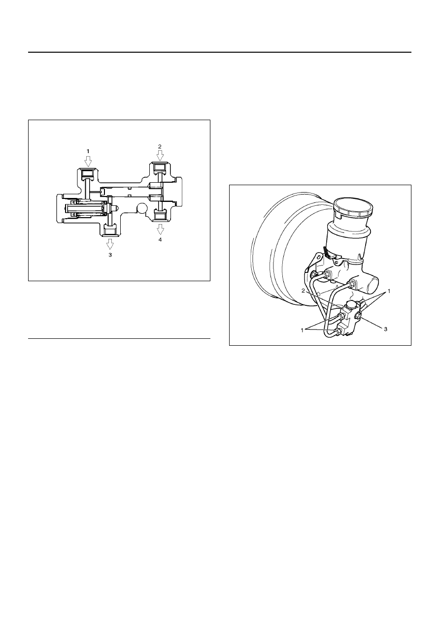
P & B (Proportioning and Bypass) Valve
P & B (Proportioning and Bypass)
Valve Sectional View
350RW014
EndOFCallout
The P&B valve contains two sections, each serving a
different function.
The proportioning section of the P&B valve proportions
outlet pressure to the rear brakes after a predetermined
rear input pressure has been reached. This is done to
prevent rear wheel lock up on the vehicles with light rear
wheel loads. The valve has a by–pass feature which
assures full system pressure to the rear brakes in the
event of front brake system malfunction. Also full front
pressure is retained in the event of rear brake
malfunction.
The P&B valve is not repairable and must be replaced
as complete assembly.
Removal
1. The P&B valve is not repairable and must be
replaced as a complete assembly. Care must be
taken to prevent brake fluid from contacting any
painted surface.
2. Remove hydraulic pipes (1) and plug the pipes (1)
to prevent the loss of fluid or the entrance of dirt.
3. Remove bolt (3).
4. Remove P&B valve (2).
350R200003
Installation
1. Install P&B valve (2).
2. Install bolt (3) and tighten the bolt to the specified
torque.
Torque: 22 N·m (16 lb ft)
3. Install hydraulic pipes (1) and tighten the bolt to the
specified torque.
Torque: 12 N·m (104 lb in)
4. After installing the brake pipes, bleed the brakes as
described in Bleeding Brake Hydraulic System in
this section.
Legend
(1) Master Cylinder (Secondary)
(2) Master Cylinder (Primary)
(3) Rear Brake
(4) Front Brake