Content .. 1168 1169 1170 1171 ..
Isuzu Amigo / Axiom / Trooper / Rodeo / VehiCross. Manual - part 1170
BRAKE CONTROL SYSTEM
5A–9
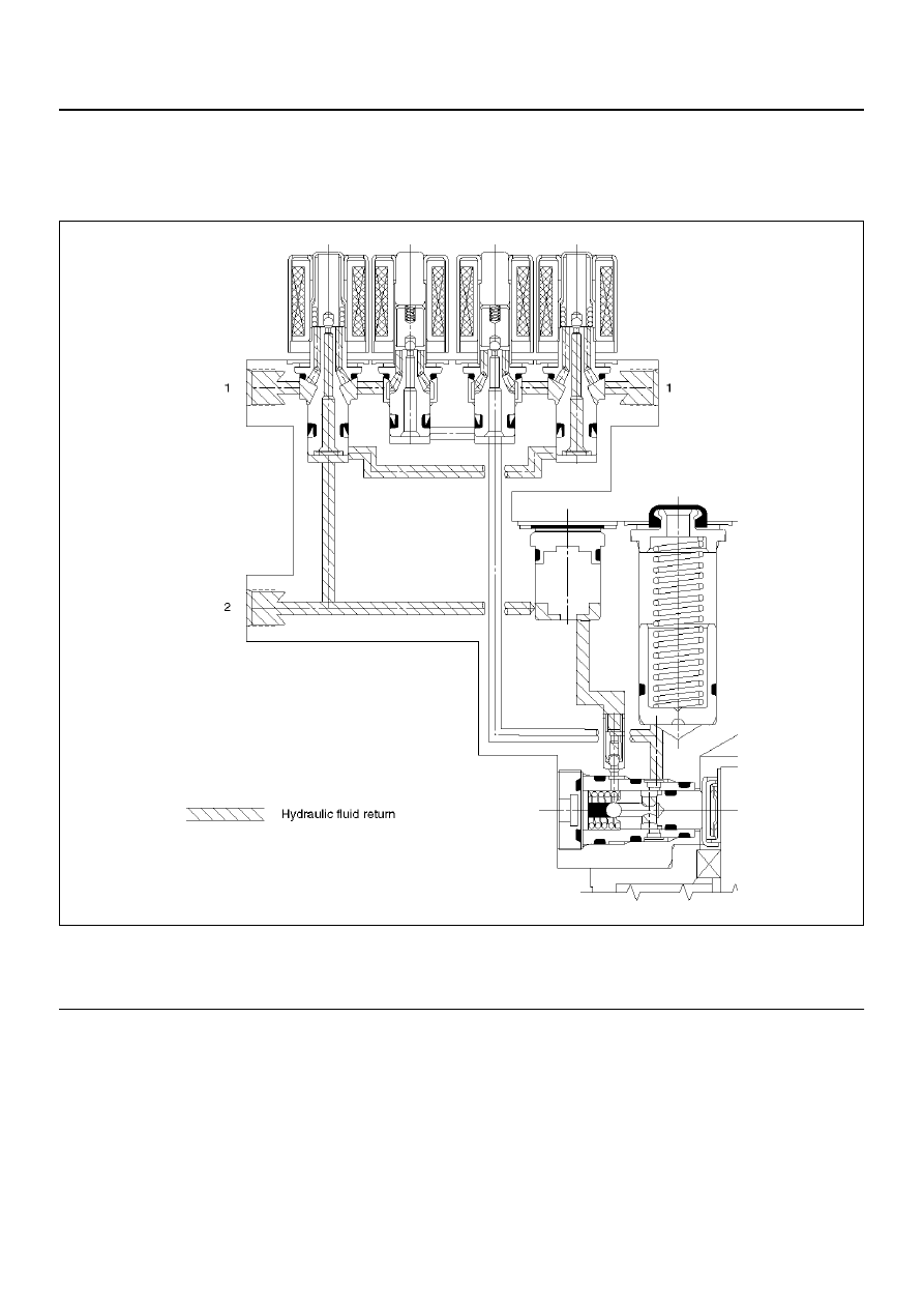
Brake Release
At the end of the anti-lock stop, when the brake pedal is
released, the pump will remain running for a short time
to help drain any fluid from the accumulators. As this
fluid returns into the system, the spring forces the piston
back to its original position.
The isolation valve opens and fluid may return to the
master cylinder. Conventional braking is then resumed.
C05RW013
EndOFCallout
Legend
(1) Brake
(2) Master Cylinder