Content .. 1145 1146 1147 1148 ..
Isuzu Amigo / Axiom / Trooper / Rodeo / VehiCross. Manual - part 1147
DRIVELINE CONTROL SYSTEM
4B–21
Installation
1. Connect harness connector, then install 4WD
control unit.
2. Install center console assembly.
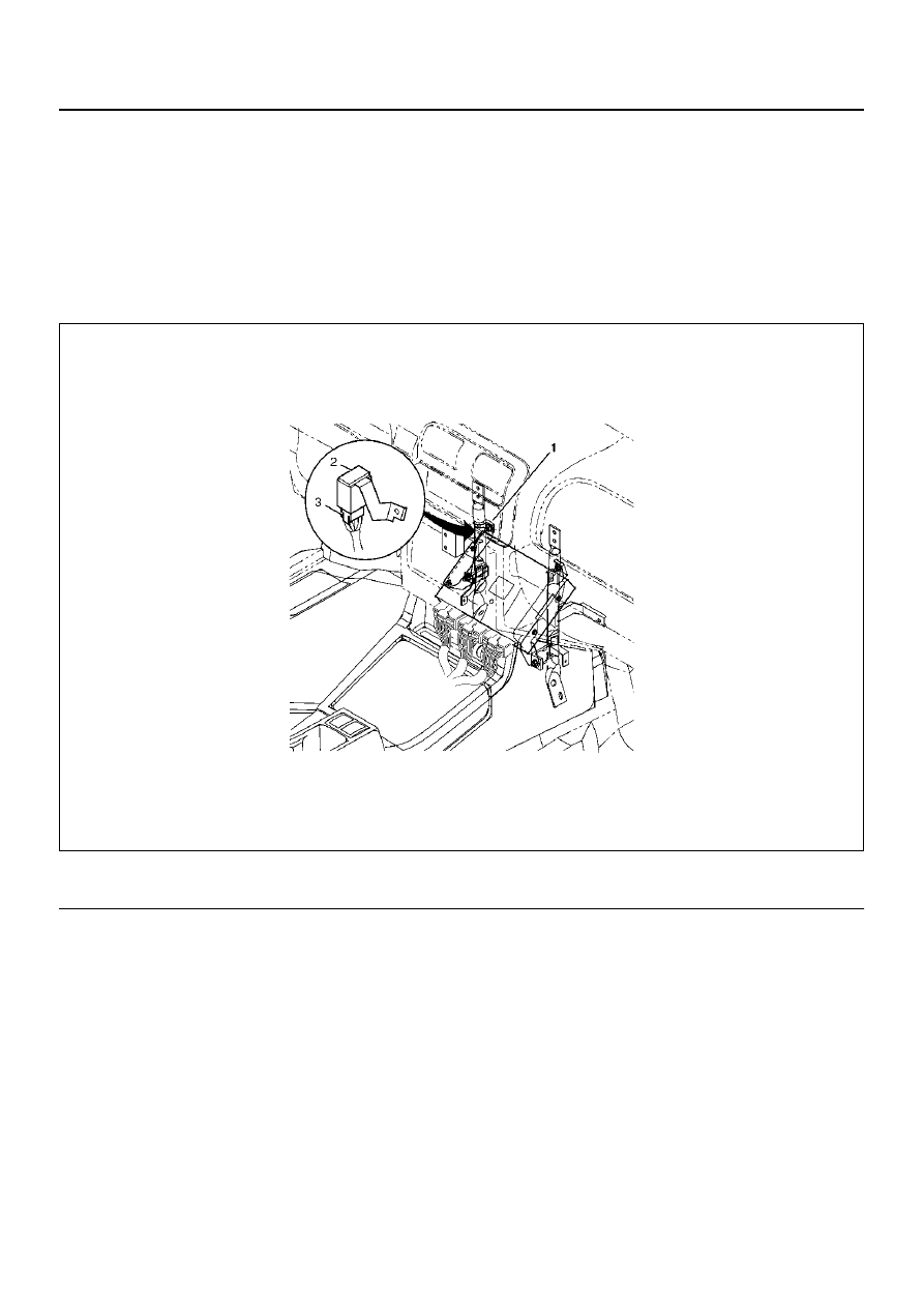
Shift On The Fly Controller
Shift On The Fly Controller and Associated Parts
828RY00003
EndOFCallout
Removal
1. Disconnect the battery ground cable.
2. Remove the front console assembly.
Refer to Consoles in Body and Accessories section.
3. Disconnect the connector from the controller.
4. Remove the nut.
5. Remove the controller.
Installation
To install, follow the removal steps in the reverse order,
noting the following points.
Torque: Nut (1) 8 N·m (69 Ib in)
Legend
(1) Nut
(2) SOF Controller
(3) Connector