Isuzu Amigo / Axiom / Trooper / Rodeo / VehiCross. Manual - part 1139


  Index      Isuzu     Isuzu Amigo / Axiom / Trooper / Rodeo / VehiCross - service repair manual 1999-2002 year


Search            


Content   ..  1137  1138  1139  1140   ..


Isuzu Amigo / Axiom / Trooper / Rodeo / VehiCross. Manual - part 1139


4A2–24

DIFFERENTIAL (REAR)

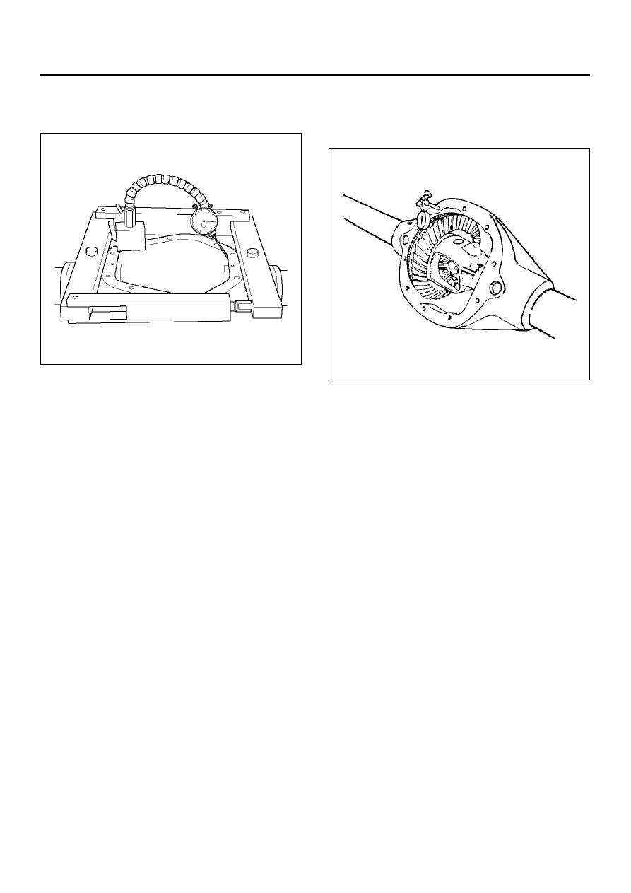
11. Assembly the spreader J–24385–B and indicator to

the carrier as shown in figure. Spread the carrier
0.5mm (0.02 in) for differential installation.

420RW004

CAUTION:  Do not spread the carrier over 0.5 mm
(0.02 in).

12. Remove the indicator.

Backlash Adjustment

1. Install the differential case assembly and bearing

caps.

2. Rotate the case several times to seat the bearings.

3. Remove the spreader.

4. Install the side bearing cap bolts.

Tighten side bearing cap bolts

Torque: 108 N·m (80 lb ft)

5. Install a dial indicator to the case using a magnetic

base.

6. Place the indicator stem at the heel end of a tooth.

• Set the dial indicator so that the stem is in line

with the gear rotation and perpendicular to the
tooth angle.

425RS087

7. Check and record the backlash at three points

around the ring gear.

• The pinion must be held stationary when

checking backlash.

• The backlash should be the same at each point

within 0.07mm (0.003in).   If the backlash varies
more than 0.07 mm (0.003in), check for burrs, a
distorted case flange, or uneven bolting
conditions.

8. Backlash at the minimum lash point measured

should be between 0.13 and 0.20mm (0.005 and
0.008 in) for all new gear sets.

9. If the backlash is not  within specifications, move the

ring gear in or out from the pinion by increasing the
thickness of one shims, and decreasing the
thickness of the other shim by the same amount.
This will maintain the correct rear axls side bearing
preload.

• Moving 0.05 mm (0.002 in) worth of shim from one

side of the differential to the other will change the
backlash adjustment by 0.03mm (0.001 in). 

10. After obtaining correct tooth contact described in

later, install ABS speed sensor.

11. Install the cover with sealant.

Torque: 40 N·m (30 lb ft)

12. Fill the axle lubricant.

DIFFERENTIAL (REAR)

4A2–25

Gear Tooth Pattern Check

Checking the ring gear to pinion tooth pattern is to be
done only after setting up the axle according to the
methods in this section.   The pattern check is NEVER
to be used as an initial check, or instead of checking
pinion depth and backlash adjustments.
This check is only to be verify the correct adjustment of
the gear set after set up.

425RS038

EndOFCallout

1. Wipe all oil out of the carrier, and carefully clean

each tooth of the ring gear.

2. Use gear marking compound 1052351 or equivalent

and apply this mixture sparingly to all ring gear
teeth,   using a medium-stiff brush. When properly
used, the area of pinion tooth contact will be visible
when hand load is applied.

3. Tighten the bearing cap bolts to the specified

torque.

4. Expand the brake shoes until a torque of 54 to

68 N·m (40 to 50 lbft.) is required to turn the pinion.
A test made without loading the gears will not give a
satisfactory pattern.   Turn the pinion flange with a
wrench so that the ring gear rotates one full
revolution, then reverse the rotation so that the ring
gear rotates one revolution in the opposite direction.

5. Observe the pattern on the ring gear teeth and

compare this with figure.

425RS039

 Legend  

(1) Heel
(2) Toe
(3) Concave Side (Coast)
(4) Convex Side (Drive)

4A2–26

DIFFERENTIAL (REAR)

Adjustments Affecting Tooth Contact

Two adjustments can be made which will affect tooth
contact pattern: backlash, and the position of the drive
pinion in the case.   The effects of bearing preloads are
not readily apparent on head loaded tooth contact
pattern tests; however,   these adjustments should be
within specifications before proceeding with backlash
and drive pinion adjustments.
The position of the drive pinion is adjusted by increasing
or decreasing the distance between the pinion head and
the centerline of the ring gear.
Decreasing the distance will move the pinion closer to
the centerline of the ring gear. Increasing the distance

will move the pinion farther away from the centerline of
the ring gear.
Backlash is adjusted by means of the side bearing
adjusting shims which move the entire case and ring
gear assembly closer to, or farther from, the drive
pinion. (The adjusting shims are also used to set side
bearing preload.)
If the thickness of the right shim is increased (along with
decreasing the left shim thickness), backlash will
increase.
The backlash will decrease if the left shim thickness is
increased (along with a decrease in right shim
thickness).

Differential Case Assembly

Disassembled View

425RW014

EndOFCallout

 Legend  

 (1)  Thrust Washer (for Pinion Gear) 
 (2)  Pinion Mate Gear 
 (3)  Thrust Washer(for Side Gear) 
 (4)  Side Gear 

 (5)  Differential Shaft 
 (6)  Lock Pin 
 (7)  Bolt 
 (8)  Differential Case 

DIFFERENTIAL (REAR)

4A2–27

Disassembly

1. Remove lock pin using a small drift.

425RS098

2. Remove the differential shaft by using a soft metal

rod and a hammer. 

 425RS043

3.  Remove pinion mate gear and thrust washer. 

4.  Remove side gear and thrust washer. 

Inspection and Repair

 Make necessary correction or parts replacement if
wear, damage, corrosion or any other abnormal
condition are found through inspection. 
 Check the following parts. 

• Ring gear, pinion gear

• Bearing

• Side gear, pinion mate gear, differential shaft

• Differential case, carrier

• Thrust washer

• Oil seal

Reassembly

1. Install side gear with thrust washer.

2. Install the pinion mate gear with thrust washer by

engaging it with the side gears while turning both
pinion mate gears simultaneously in the same
direction. 

425RS048

3. Install differential shaft.

1. Be sure to install the differential shaft so that it is

in alignment with the lock pin hole in the
differential case.

425RS049

4. Install lock pin.

After lock pin installation, stake the case to secure
the lock pin.


Content   ..  1137  1138  1139  1140   ..