Content .. 1107 1108 1109 1110 ..
Isuzu Amigo / Axiom / Trooper / Rodeo / VehiCross. Manual - part 1109
FRONT SUSPENSION
3C–23
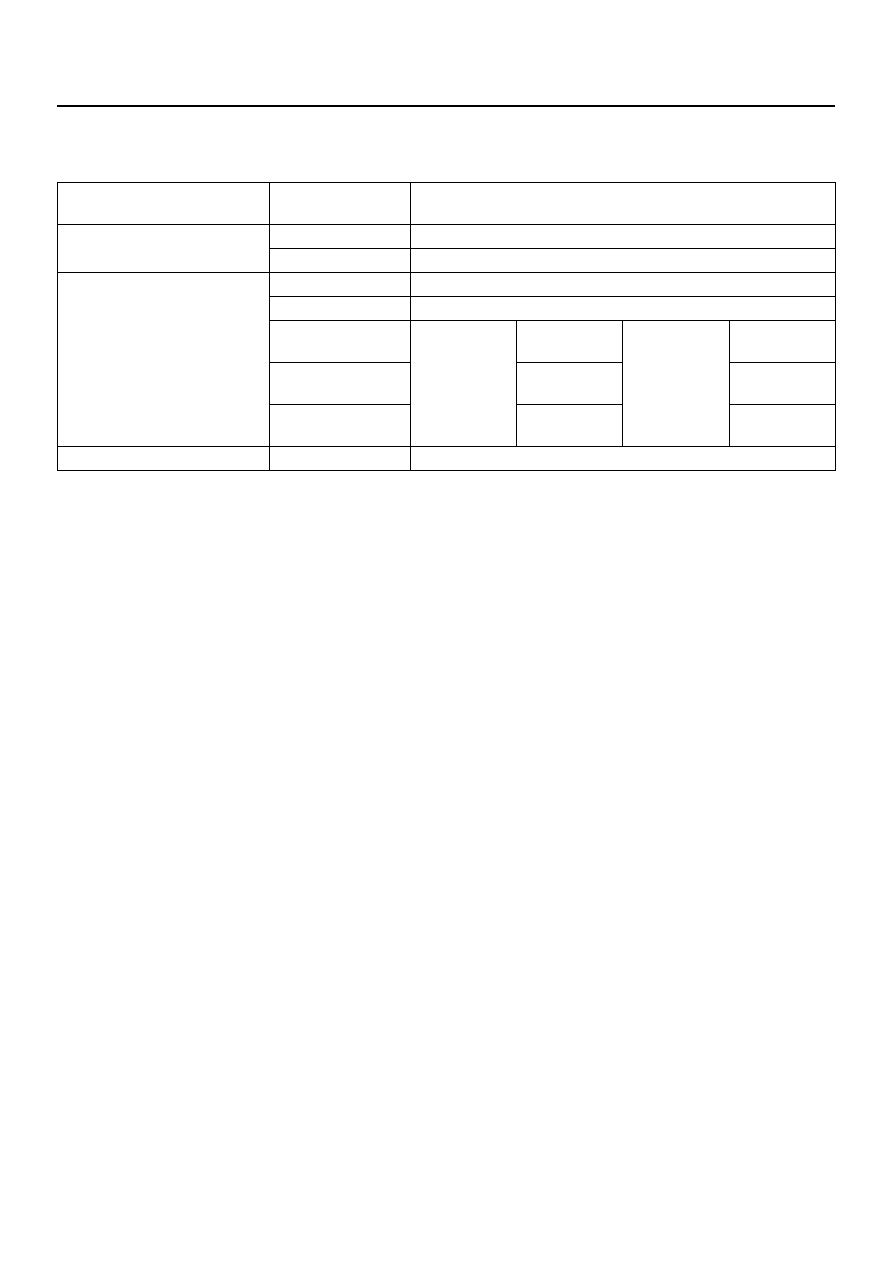
Main Data and Specifications
General Specifications
Front suspension
Type
Independent wishbone arms, torsion bar spring with stabilizer
bar.
Torsion bar spring
Length
1142 mm (45.0in)
Diameter
27.0 mm (1.06 in)
Front shock absorber
Type
Hydraulic, double acting, telescopic
Piston diameter
30.0 mm (1.18 in)
Stroke
Without ISC
shock
absorber
125.0 mm
(4.92 in)
With ISC
shock
absorber
120.0mm
(4.72in)
Compressed
length
255.0 mm
(10.04in)
261.0mm
(10.28 in)
Extended length
380.0 mm
(14.96in)
381.0mm
(15.0in)
Stabilizer bar
Diameter
25.0 mm (0.98 in)