Isuzu Amigo / Axiom / Trooper / Rodeo / VehiCross. Manual - part 1101


  Index      Isuzu     Isuzu Amigo / Axiom / Trooper / Rodeo / VehiCross - service repair manual 1999-2002 year


Search            


Content   ..  1099  1100  1101  1102   ..


Isuzu Amigo / Axiom / Trooper / Rodeo / VehiCross. Manual - part 1101


POWER-ASSISTED STEERING SYSTEM

2A–41

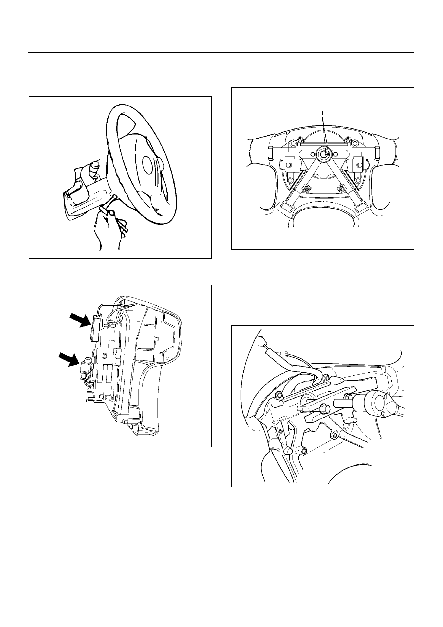
7. Loosen the inflator module fixing bolt from behind 

the steering wheel assembly using a TORX® driver 
or equivalent until the inflator module can be 
released from steering assembly.

827RW070

8. Disconnect the yellow 2-way SRS connector and 

horn lead located behind the inflator module.

827RW073

9. Apply a setting mark (1) across the steering wheel 

and shaft so parts can be reassembled in their 
original position.

430RW021

10. Move the front wheels to the straight ahead position, 

then use steering wheel remover J–29752 to 
remove the steering wheel. 

CAUTION:  Never apply force to the steering wheel 
shaft using a hammer or other impact tools in an   
attempt to remove the steering wheel. The steering 
shaft is designed as an energy absorbing unit.

430RX005

2A–42

POWER-ASSISTED STEERING SYSTEM

WARNING:  THE INFLATOR MODULE SHOULD 
ALWAYS BE CARRIED WITH THE TRIM COVER 
AWAY FROM YOUR BODY AND SHOULD ALWAYS 
BE LAID ON A FLAT SURFACE WITH THE 
URETHANE SIDE UP.   THIS IS NECESSARY 
BECAUSE FREE SPACE IS PROVIDED TO ALLOW 
THE AIR CUSHION TO EXPAND IN THE UNLIKELY 
EVENT OF ACCIDENTAL DEPLOYMENT. 
OTHERWISE, PERSONAL INJURY MAY RESULT.

827RW072

11. Remove steering column cover.

12. Disconnect the wiring harness connectors located 

under the steering column.

13. Remove the combination switch assembly with SRS 

coil.

825RW288

14. Remove snap ring.

15. Remove cushion rubber.

16. Remove shift lock cable (for A/T).

17. Disconnect the starter switch harness connector 

located under the steering column then remove lock 
cylinder assembly.

Installation

1. Install lock cylinder assembly.

2. Install shift lock cable (for A/T).

3. Install cushion rubber.

4. Install snap ring.

5. Install Combination switch and SRS coil assembly.   

After installation of combination switch assembly, 
connect the combination switch wiring harness 
connector and the SRS 2-way connector located 
under the steering column.

6. Turn the SRS coil counter clockwise to full, return 

about 3 turns and align the neutral mark.

CAUTION:  Turn the SRS coil counter clockwise 
until some resistance is felt, or damage may occur 
to   the SRS coil.

825RW016

POWER-ASSISTED STEERING SYSTEM

2A–43

7. When installing the steering column cover, be sure 

to wire (through each harness) as illustrated so that 
the harnesses starter switch, combination switch 
and SRS coil may not catch wiring.

825RW017

E nd OFCa llou t

8. Install steering wheel by aligning the setting marks 

made during removal.

CAUTION:  Never apply force to the steering wheel 
shaft using a hammer or other impact tools in an   
attempt to remove the steering wheel. The steering 
shaft is designed as an energy absorbing unit.

9. Tighten the steering wheel fixing nut to the specified 

torque.

Torque: 34 N·m  (25 lb ft)

10. Support inflator module and carefully connect the 

SRS connector and horn lead, then install inflator 
module.

NOTE:  Pass the lead wire through the tabs on the 
plastic cover (wire protector) of inflator to prevent lead 
wire from being pinched.

11. Tighten fixing bolts to specified torque.

Torque: 9 N·m (78lb in)

12. Install driver knee bolster (reinforcement).

13. Install instrument panel lower cover, then install the 

engine hood opening lever.

14. Connect the yellow 2-way SRS connector located 

under the steering column.

15. Connect the battery ground cable.

System Inspection

Turn the ignition switch to the “ON" position and 
observe the warning lamp. The lamp should flash 7   
times. If the lamp does not operate correctly, refer to 
Restraints section.

Legend

(1)

Steering Column Cover

(2)

Starter Switch Harness

(3)

Combination Switch Harness

(4)

Inflator Module Harness

2A–44

POWER-ASSISTED STEERING SYSTEM

Steering Column

Steering Column and Associated Parts

431RX004

E nd O FCallo ut

Removal

1. Turn the steering wheel so that the vehicle's wheels 

are pointing straight ahead.

2. Turn the ignition switch to “LOCK".

3. Disconnect the battery ground cable, and wait at 

least 5 minutes.

4. Disconnect the yellow 2-way SRS connector located 

under the steering column.

CAUTION:  The wheel of the vehicle must be 
straight ahead and the steering column in the 
“LOCK" position before disconnecting the steering 
column from the steering gear. Failure to do so will 
cause the SRS coil assembly to become uncentered 
which will cause damage to the SRS coil assembly.

Legend

(1)

Inflator Module

(2)

Steering Wheel

(3)

Steering Column Cover

(4)

Combination Switch and SRS Coil Assembly

(5)

Snap Ring

(6)

Cushion Rubber

(7)

Lock Cylinder Assembly

(8)

Shift Lock Cable (For A/T)

(9)

Steering Column Assembly

(10)

Second Steering Shaft

(11)

Instrument Panel Lower Cover

(12)

Driver Knee Bolster (reinforcement)


Content   ..  1099  1100  1101  1102   ..