Isuzu Amigo / Axiom / Trooper / Rodeo / VehiCross. Manual - part 1089


  Index      Isuzu     Isuzu Amigo / Axiom / Trooper / Rodeo / VehiCross - service repair manual 1999-2002 year


Search            


Content   ..  1087  1088  1089  1090   ..


Isuzu Amigo / Axiom / Trooper / Rodeo / VehiCross. Manual - part 1089


1A–78 HEATING, VENTILATION AND AIR CONDITIONING (HVAC)

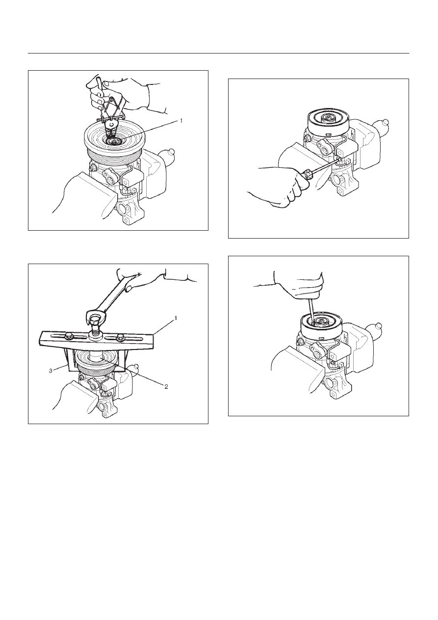
4. Remove snap ring (1) by using snap ring pliers.

871RY00029

5. Remove pulley assembly by using pulley puller pilot

J-38424 (2), pulley puller J-8433 (1) and pulley puller
leg J-24092-2 (3).

871RY00033

6. Loosen screw and disconnect the field coil wire

connector.

871RY00030

7. Loosen three screws and remove the field coil.

871RY00034

HEATING, VENTILATION AND AIR CONDITIONING (HVAC) 1A–79

Inspection and Repair

Drive Plate

If the frictional surface shows signs of damage due to
excessive heat, the drive plate and pulley should be
replaced.

Pulley Assembly

Check the appearance of the pulley assembly.  If the
frictional surface of the pulley shows signs of excessive
grooving due to slippage, both the pulley and drive plate
should be replaced.  The frictional surfaces of the pulley
assembly should be cleaned with a suitable solvent
before reinstallation.

Coil

Check coil for loose connector or cracked insulation.

Installation

1. Install field coil.

D

Align the located portion (1) of the field coil and
compressor.

871RY00035

D

Tighten the mounting screw to the specified torque.

Torque: 5N·m (44 lb in)

2. Connect the lead wire connector with the rubber hold

and tighten the screw.

3. Install pulley assembly by using pulley installer

J-33940-A (2) and drive handle J-8092 (1).

871RY00032

4. Install snap ring.
5. Install shim (s).
6. Install the drive plate to the compressor drive shaft

together with the original shim(s)(1).  Press the drive
plate by hand.

871RY00031

1A–80 HEATING, VENTILATION AND AIR CONDITIONING (HVAC)

7. Install drive plate bolt by using drive plate holder

J-33939 (1) to prevent the drive plate from rotating.

871RX029

D

Tighten the drive plate bolt to the specified torque.

Torque: 13 N·m (113 lb in)

D

After tightening the drive plate bolt, check to be sure
the pulley rotates smoothly.

D

Check to be sure that the clutch clearance is
between 0.3-0.6 mm (0.01-0.02 in.)

871RY00028

Legend

(1) Dial Gauge
(2) Pulley Assembly
(3) Field Coil Wire Connector

D

If necessary, install adjusting shim(s).

D

Adjusting shims are available in the following
thickness.

Thickness

D

0.1 mm (0.0039 in.)

D

0.3 mm (0.0118 in.)

D

0.5 mm (0.0197 in.)

HEATING, VENTILATION AND AIR CONDITIONING (HVAC) 1A–81

Compressor Oil

Oil Specification

D

The HFC-134a system requires a synthetic (PAG)
compressor oil whereas the R-12 system requires a
mineral compressor oil. The two oils must never be
mixed.

D

Compressor (PAG) oil varies according to
compressor model. Be sure to use oil specified for the
model of compressor.

D

Always use HFC-134a Vane Rotary Type
Compressor Oil (AIPDN Part No.2-90188-301-0)

Handling of Oil

D

The oil should be free from moisture, dust, metal
powder, etc.

D

Do not mix with other oil.

D

The water content in the oil increases when exposed
to the air. After use, seal oil from air immediately.
(HFC-134a Vane Rotary Compressor Oil absorbs
moisture very easily.)

D

The compressor oil must be stored in steel
containers, not in plastic containers.

Compressor Oil Check

The oil used to lubricate the compressor is circulating with
the refrigerant.
Whenever replacing any component of the system or a
large amount of gas leakage occurs, add oil to maintain
the original amount of oil.

Oil Capacity
Capacity total in system: 150cc (5.0 fl.oz)
Compressor (Service parts) charging amount:
150 cc (5.0 fl.oz)

Checking and Adjusting Oil Quantity
for Used Compressor

1. Perform oil return operation. Refer to Oil Return

Operation in this section.

2. Discharge and recover refrigerant and remove the

compressor.

3. Drain the compressor oil and measure the extracted

oil with a measuring cylinder.

4. If the amount of oil drained is much less than 90 cc

(3.0 fl. oz.), some refrigerant may have leaked out.
Conduct a leak tests on the connections of each
system, and if necessary, repair or replace faulty
parts.

5. Check the compressor oil contamination. (Refer to

Contamination of Compressor Oil in this section.)

6. Adjust the oil level following the next procedure

below.

(Charging Amount)

(Collected Amount)

more than 90cc (3.0
fl.oz)

same as collected
amount

less than 90 cc (3.0 fl.oz)

90cc (3.0 fl.oz)

7. Install the compressor, then evacuate, charge and

perform the oil return operation.

8. Check system operation.

When it is impossible to preform oil return operation,
the compressor oil should be checked in the
following order:

1. Discharge and recover refrigerant and remove the

compressor.

2. Drain the compressor oil and measure the extracted

oil with a measuring cylinder.

3. Check the oil for contamination.
4. If more than 90 cc (3.0 fl. oz.) of oil is extracted from

the compressor, supply the same amount of oil to the
compressor to be installed.

5. If the amount of oil extracted is less than 90 cc (3.0 fl.

oz.), recheck the compressor oil in the following
order.

6. Supply 90 cc (3.0 fl. oz.) of oil to the compressor and

install it onto the vehicle.

7. Evacuate and recharge with the proper amount of

refrigerant.

8. Perform the oil return operation.
9. Remove the compressor and recheck the amount of

oil.

10. Adjust the compressor oil, if necessary.

(Collected Amount)

(Charging Amount)

more than 90 cc (3.0
fl.oz)

same as collected
amount

less than 90 cc (3.0 fl.oz)

90 cc (3.0 fl.oz)


Content   ..  1087  1088  1089  1090   ..