Isuzu Amigo / Axiom / Trooper / Rodeo / VehiCross. Manual - part 1086


  Index      Isuzu     Isuzu Amigo / Axiom / Trooper / Rodeo / VehiCross - service repair manual 1999-2002 year


Search            


Content   ..  1084  1085  1086  1087   ..


Isuzu Amigo / Axiom / Trooper / Rodeo / VehiCross. Manual - part 1086


1A–66 HEATING, VENTILATION AND AIR CONDITIONING (HVAC)
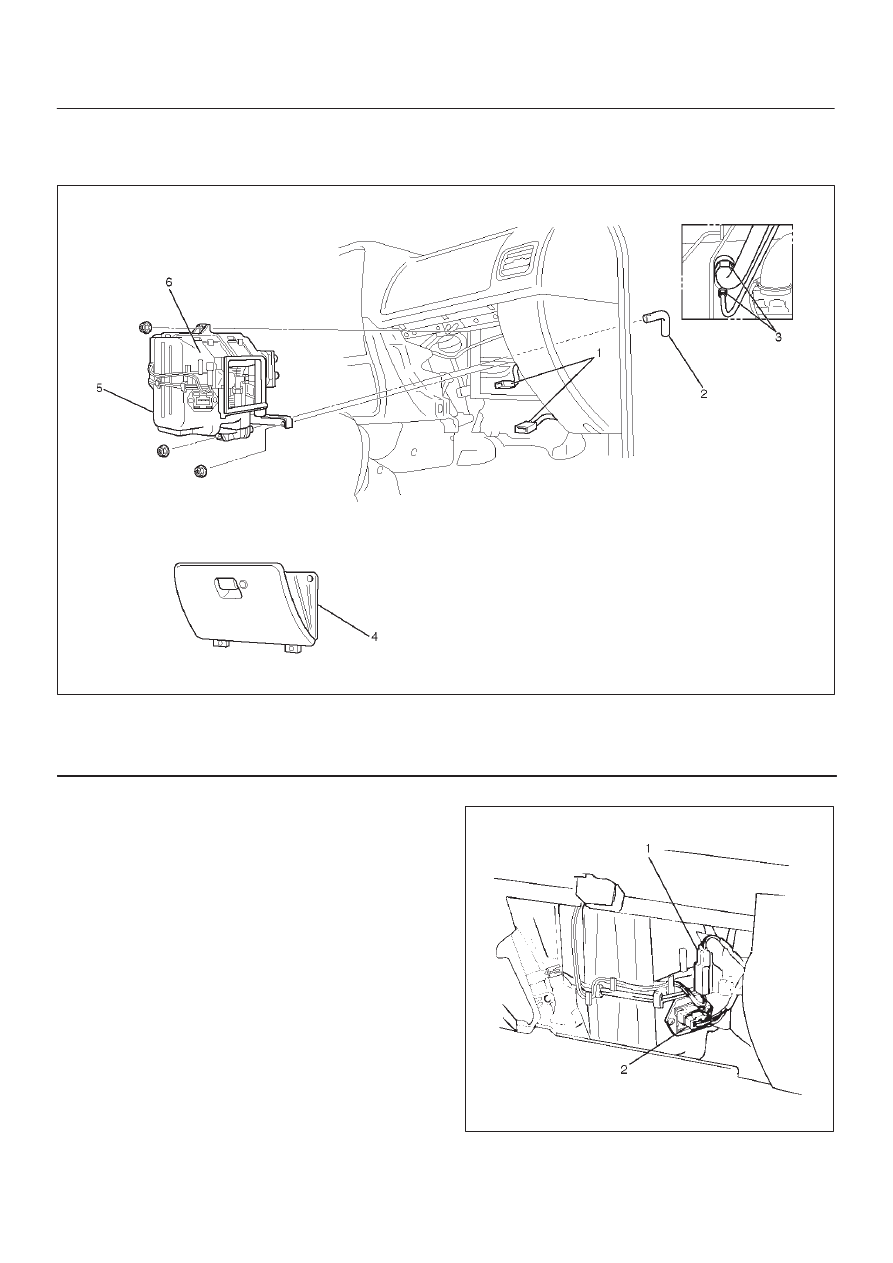
Evaporator Assembly

Evaporator Assembly and Associated Parts

874RY00017

Legend

(1) Resistor and Electronic Thermostat Connector
(2) Drain Hose

(3) Refrigerant Line
(4) Glove Box
(5) Evaporator Assembly

Removal

1. Disconnect the battery ground cable.
2. Discharge and recover refrigerant.

D

Refer to Refrigerant Recovery in this section.

3. Remove glove box.
4. Disconnect resistor (2) and electronic thermostat

connector (1).

874RY00021

HEATING, VENTILATION AND AIR CONDITIONING (HVAC) 1A–67

5. Disconnect drain hose.
6. Disconnect refrigerant line.

D

Use a back-up wrench when disconnecting and
reconnecting the refrigerant lines.

D

When removing the refrigerant line connected part,
the connecting part should immediately be plugged
or capped to prevent foreign matter from being
mixed into the line.

7. Remove evaporator assembly.

Installation

To install, follow the removal steps in the reverse order,
noting the following points:

1. To install a new evaporator assembly, add 50cc

(1.7 fl. oz.) of new compressor oil to the new core.

2. Tighten the refrigerant outlet line to the specified

torque.

Torque: 25 N

m (18 lb ft)

3. Tighten the refrigerant inlet line to the specified

torque.

Torque: 15 N

m (11 lb ft)

4. O-rings cannot be reused. Always replace with new

ones.

5. Be sure to apply new compressor oil to the O-rings

when connecting lines.

1A–68 HEATING, VENTILATION AND AIR CONDITIONING (HVAC)

Electronic Thermostat, Evaporator Core and/or Expansion Valve

Disassembled View

874RX001

Legend

(1) Lining
(2) Expansion Valve
(3) O-ring
(4) Evaporator Assembly
(5) Lower Case

(6) Clip
(7) Attaching Screw
(8) Evaporator Core
(9) Electronic Thermostat

(10) Upper Case

Removal

1. Disconnect the battery ground cable.
2. Discharge and recover refrigerant.

D

Refer to Refrigerant Recovery in this section.

3. Remove evaporator assembly.

D

Refer to Evaporator Assembly in this section.

4. Remove the electronic thermostat sensor fixing clip.

Pull the sensor from the evaporator assembly.

5. Remove clip.
6. Remove attaching screw.
7. Remove upper case.
8. Remove lower case.

D

Slit the case parting face with a knife since the lining
is separated when removing the evaporator.

874RS006

HEATING, VENTILATION AND AIR CONDITIONING (HVAC) 1A–69

D

Lift to remove the upper case.

874R100002

9. Remove evaporator core.

874R100001

10. Remove expansion valve.

D

Tear off the insulator carefully.

D

Remove the sensor fixing clip.

D

Use a back-up wrench when disconnecting all
refrigerant pipes.

Installation

To install, follow the removal steps in the reverse order,
noting the following points:

1. The sensor is installed on the core with the clip.
2. The sensor must not interfere with the evaporator

core.

3. When installing the new evaporator core, install the

duct sensor (2) to the evaporator core (1) specified
position with the clip in the illustration.

874RY00016

4. O-rings cannot be reused. Always replace with new

ones.

5. Be sure to apply new compressor oil to the O-rings

when connecting lines.

6. Be sure to install the sensor and the insulator on the

place where they were before.

7. To install a new evaporator core, add 50cc (1.7 fl. oz.)

of new compressor oil to the new core.

8. Tighten the refrigerant lines to the specified torque.

Refer to Main Data and Specifications for Torque
Specifications in this section.

9. Apply an adhesive to the parting face of the lining

when assembling the evaporator assembly.


Content   ..  1084  1085  1086  1087   ..