Content .. 1081 1082 1083 1084 ..
Isuzu Amigo / Axiom / Trooper / Rodeo / VehiCross. Manual - part 1083
1A–54 HEATING, VENTILATION AND AIR CONDITIONING (HVAC)
3. If the leak is still present, discharge and recover the
refrigerant from the system.
4. Replace the O-rings.
D
O-rings cannot be reused. Always replace with new
ones.
D
Be sure to apply the specified compressor oil to the
new O-rings.
5. Retighten the refrigerant line fitting to the specified
torque.
D
Use two wrenches to prevent twisting and damage
to the line.
6. Evacuate, charge and retest the system.
Leaks In The Hose
If the compressor inlet or outlet hose is leaking, the entire
hose must be replaced. The refrigerant hose must not be
cut or spliced for repair.
1. Locate the leak.
2. Discharge and recover the refrigerant.
3. Remove the hose assembly.
D
Cap the open connections at once.
4. Connect the new hose assembly.
D
Use two wrenches to prevent twisting or damage to
the hose fitting.
D
Tighten the hose fitting to the specified torque.
5. Evacuate, charge and test the system.
Compressor Leaks
If leaks are located around the compressor shaft seal or
shell, replace or repair the compressor.
Recovery, Recycling, Evacuation and
Charging of HFC-134a
Air conditioning systems contain HFC-134a. This is a
chemical mixture which requires special handling
procedures to avoid personal injury.
D
Always wear safety goggles and protective gloves.
D
Always work in a well-ventilated area. Do not weld or
steam clean on or near any vehicle-installed air
conditioning lines or components.
D
If HFC-134a should come in contact with any part of
the body, flush the exposed area with cold water and
immediately seek medical help.
D
If it is necessary to transport or carry any container of
HFC-134a in a vehicle, do not carry it in the
passenger compartment.
D
If it is necessary to fill a small HFC-134a container
from a large one, never fill the container completely.
Space should always be allowed above the liquid for
expansion.
D
HFC-134a and R-12 should never be mixed as their
compositions are not the same.
D
HFC-134a PAG oil tends to absorb moisture more
quickly than R-12 mineral oil and, therefore, should
be handled more carefully.
D
Keep HFC-134a containers stored below 40
°
C
(104
°
F).
WARNING:
D
SHOULD HFC-134A CONTACT YOUR EYE(S),
CONSULT A DOCTOR IMMEDIATELY.
D
DO NOT RUB THE AFFECTED EYE(S). INSTEAD,
SPLASH QUANTITIES OF FRESH COLD WATER
OVER THE AFFECTED AREA TO GRADUALLY
RAISE THE TEMPERATURE OF THE
REFRIGERANT ABOVE THE FREEZING POINT.
D
OBTAIN PROPER MEDICAL TREATMENT AS
SOON AS POSSIBLE. SHOULD THE HFC-134A
TOUCH THE SKIN, THE INJURY MUST BE
TREATED THE SAME AS SKIN WHICH HAS BEEN
FROSTBITTEN OR FROZEN.
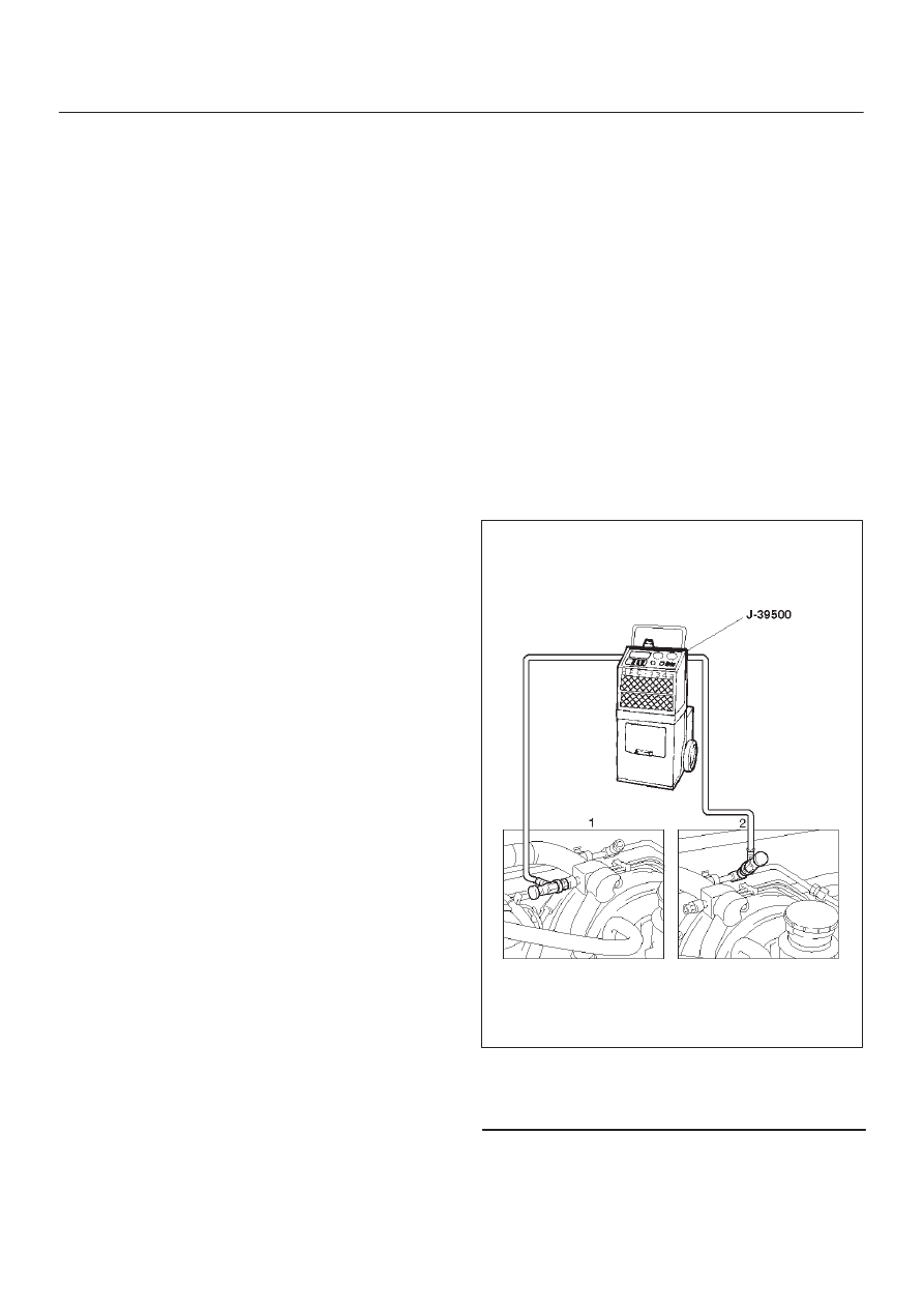
Refrigerant Recovery
The refrigerant must be discharged and recovered by
using the J-39500 (ACR
4
:HFC-134a Refrigerant
Recovery/Recycling/Recharging/System) or equivalent
before removing or mounting air conditioning parts.
1. Connect the high and low charging hoses of the
ACR
4
(or equivalent) as shown below.
901R100022
Legend
(1) Low Side
(2) High Side
2. Recover the refrigerant by following the
Manufacturer’s Instructions.
3. When a part is removed, put a cap or a plug on the
connecting portion so that dust, dirt or moisture
cannot get into it.