Isuzu Amigo / Axiom / Trooper / Rodeo / VehiCross. Manual - part 108
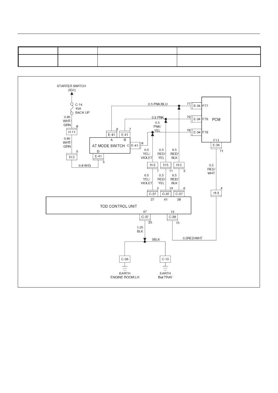
DRIVE LINE CONTROL SYSTEM (TOD)
4B2–50
Check flow
Trouble code
Phenomenon
Standard
8
17 (P1774)
The input from the mode switch is
abnormal.
—
D04R200025
Index Isuzu Isuzu Amigo / Axiom / Trooper / Rodeo / VehiCross - service repair manual 1999-2002 year
|
|
|
DRIVE LINE CONTROL SYSTEM (TOD) 4B2–50 Check flow Trouble code Phenomenon Standard 8 17 (P1774) The input from the mode switch is abnormal. — D04R200025 |