Isuzu Amigo / Axiom / Trooper / Rodeo / VehiCross. Manual - part 1049


  Index      Isuzu     Isuzu Amigo / Axiom / Trooper / Rodeo / VehiCross - service repair manual 1999-2002 year


Search            


Content   ..  1047  1048  1049  1050   ..


Isuzu Amigo / Axiom / Trooper / Rodeo / VehiCross. Manual - part 1049


SUPPLEMENTAL RESTRAINT SYSTEM

9J–37

Steering Column

Service Precautions

WARNING: SAFETY PRECAUTIONS MUST BE
FOLLOWED WHEN HANDLING A DEPLOYED AIR
BAG ASSEMBLY. AFTER DEPLOYMENT, THE AIR
BAG ASSEMBLY SURFACE MAY CONTAIN A SMALL
AMOUNT OF SODIUM HYDROXIDE, A BY–PRODUCT
OF THE DEPLOYMENT REACTION, THAT IS
IRRITATING TO THE SKIN AND EYES. MOST OF THE
POWER ON THE AIR BAG ASSEMBLY IS
HARMLESS. AS A PRECAUTION, WEAR GLOVES
AND SAFETY GLASSES WHEN HANDLING A
DEPLOYED AIR BAG ASSEMBLY, AND WASH YOUR
HANDS WITH MILD SOAP AND WATER
AFTERWARDS.

WARNING: WHEN CARRYING A LIVE AIR BAG
ASSEMBLY, MAKE SURE THE BAG AND TRIM
COVER ARE POINTED AWAY FROM YOU. NEVER
CARRY AIR BAG ASSEMBLY BY THE WIRES OR
CONNECTOR ON THE UNDERSIDE OF MODULE. IN
THE CASE OF AN ACCIDENTAL DEPLOYMENT, THE
BAG WILL THEN DEPLOY WITH MINIMAL CHANCE
OF INJURY. WHEN PLACING ALIVE AIR BAG
ASSEMBLY ON A BENCH OR OTHER SURFACE,
ALWAYS FACE BAG AND RIM COVER UP, AWAY
FROM THE SURFACE. NEVER REST A STEERING
COLUMN ASSEMBLY ON THE STEERING WHEEL
WITH THE AIR BAG ASSEMBLY FACE DOWN AND
COLUMN VERTICAL. THIS IS NECESSARY SO THAT
A FREE SPACE IS PROVIDED TO ALLOW THE AIR
BAG ASSEMBLY TO EXPAND IN THE UNLIKELY
EVENT OF ACCIDENTAL DEPLOYMENT.
OTHERWISE, PERSONAL INJURY COULD RESULT.

NOTE: In the event deployment has occurred, inspect
coil assembly wire for any signs of scorching, melting or
any other damage due to excessive heat. If the coil has
been damaged, replace it.

Removal

1. Disable the SRS (Refer to “Disabling the SRS ” in this

section).

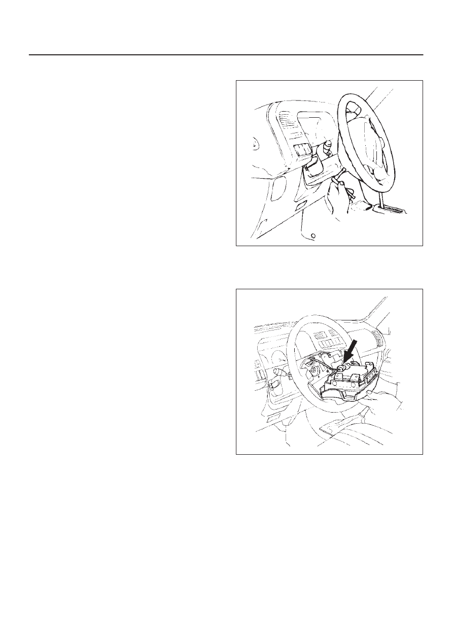
2. Loosen the air bag assembly fixing bolts from behind

the steering wheel assembly using a TORX

 driver or

equivalent until the air bag assembly can be released
from steering wheel.

827RT008

3. Disconnect the yellow 2–pin connector located

behind the air bag assembly and remove air bag
assembly.Refer to “SRS Connectors” in this section
for removal and installation.

827RT009

4. Disconnect horn lead connector.
5. Remove the steering wheel attachment nut.

SUPPLEMENTAL RESTRAINT SYSTEM

9J–38

6. Apply a setting mark across the steering wheel and

shaft so parts can be  reassembled in their original
position.

430RS004

7. Move the tires to the straight ahead position before

removing the steering wheel and removing wheel with
J–29752.

430RT009

8. Feed wiring though the wheel and remove  wheel.

9. Remove the steering lower cover and engine hood

opening lever.

10. Remove the driver knee bolster assembly.

740RT015

11. Remove the steering column cover.

12. Remove air conditioning lower duct.
13. Disconnect the wiring harness connectors located at

the base of steering column.

CAUTION: Never apply force to the steering wheel
in direction of the shaft by using a hammer or other
impact tools in an attempt to remove the steering
wheel. The steering shaft is designed as an energy
absorbing unit.

14. Remove the combination switch assembly  with SRS

coil.

NOTE: SRS coil is a part of combination switch
assembly, which cannot be replaced separately.
Therefore, be sure not to remove the SRS coil from the
combination switch assembly.

15. Remove the snap ring.
16. Remove the cushion rubber.
17. Disconnect shift lock cable (A/T only).
18. Disconnect the starter switch harness connector

located base of steering column.

19. Remove steering lock cylinder assembly.

SUPPLEMENTAL RESTRAINT SYSTEM

9J–39

20. Apply a setting mark across the universal joint and

steering shaft to reassemble the parts in their original
position.

431RS013

21. Remove steering column assembly.

Installation

1. Install the steering column assembly and align the

setting marks on the universal joint and steering shaft
made during removal.

431RS013

2. Tighten the steering column fixing bolts (dash panel

side) to the specified torque.

Torque: 20 N·m (14 lb ft)

3. Tighten the steering column fixing bolts (Pedal

bracket) to the specified torque.

Torque: 20 N·m (14 lb ft)

4. Tighten the universal joint to the  specified  torque.

Torque: 31 N·m (23 lb ft)

5. Install steering lock cylinder assembly.
6. Connect shift lock cable (For A/T)

7. Install cushion rubber.
8. Install snap ring.
9. Install the combination switch assembly with SRS

coil.

10. Connect the wiring harness connector located on the

base of steering column.

11. Turn the SRS coil counterclockwise to full, return

about 3 turns and align the neutral mark (1).

CAUTION: When turning the SRS coil
counterclockwise to full, stop turning if resistance is
felt.  Forced further  turning may damage to the cable
in the SRS coil.

826RW014

12. Install steering column cover.

CAUTION: When installing the steering column
cover, be sure to wire (through each harness) as
illustrated so that the harness starter switch,
combination switch and SRS coil may not catch
wiring.

825RS048

SUPPLEMENTAL RESTRAINT SYSTEM

9J–40

13. Install the steering wheel and align the setting marks.

430RS004

14. Tighten the steering wheel fixing nut to the specified

torque.

Torque: 34 N·m (25 lb ft)

15. Connect horn lead.
16. Connect air bag wiring harness connector.

NOTE: Pass the lead wire through the tabs on the plastic
cover (wire protector) of air bag to prevent lead wire from
being pinched.

827RT009

17. Install air bag into steering wheel and tighten bolts to

specified sequence as shown in figure.

Torque: 8.8 N·m (78 lb in)

CAUTION: Never use the air bag assembly from
another vehicle and difference model year air bag
assembly.
The air bag assembly has identification colors on the
bar code label from ’00 model as follows.
Yellow color for driver air bag assembly.
White color for passenger air bag assembly.
Use only new air bag assembly proper to the Trooper
which is being repaired.

827RT008

18. Enable the SRS (Refer to “Enabling the SRS” in this

section).


Content   ..  1047  1048  1049  1050   ..