Isuzu Amigo / Axiom / Trooper / Rodeo / VehiCross. Manual - part 1045


  Index      Isuzu     Isuzu Amigo / Axiom / Trooper / Rodeo / VehiCross - service repair manual 1999-2002 year


Search            


Content   ..  1043  1044  1045  1046   ..


Isuzu Amigo / Axiom / Trooper / Rodeo / VehiCross. Manual - part 1045


SUPPLEMENTAL RESTRAINT SYSTEM

9J–21

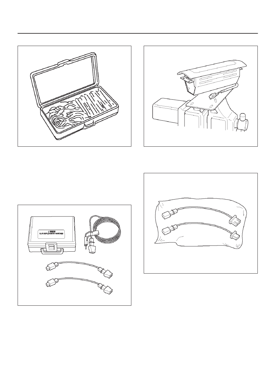
J–35616—A Connector Test Adapter Kit

901RS151

The J–35616–A Connector Test Adapter Kit must be used
whenever a diagnostic procedure requests checking or
probing a terminal.  Using the appropriate adapter will
ensure that no damage to the terminal will occur from the
DVM prove, such as spreading or bending.  The adapter
will also give an idea of whether contact tension is
sufficient, helping to find an open or intermittent open due
to poor terminal contact.

J–42986 SRS Deployment Tool

901RW106

The J–42986 SRS Deployment Tool must be used for
deployment of the undeployed air bag.

J–41497 SRS Deployment Fixture

901RW199

The J–41497 SRS Deployment Fixture must be used for
deployment of the undeployed passenger side air bag.

J–42987 SRS Adapter for Load Tool.

901RW107

The J–42987 SRS Adapter for Load Tool must be used
with J–41433 SRS Driver/Passenger Load Tool.

SUPPLEMENTAL RESTRAINT SYSTEM

9J–22

Tech 2 Scan Tool

From 98 MY, Isuzu dealer service departments are
recommended to use Tech 2. Please refer to Tech 2 scan
tool user guide.

901RW200

Legend

(1) PCMCIA Card
(2) RS 232 Loop Back Connector
(3) SAE 16/19 Adaptor
(4) DLC Cable
(5) Tech–2

Getting Started

D

Before operating the Isuzu PCMCIA card with the
Tech 2, the following steps must be performed:

1. Insert the Isuzu 98 System PCMCIA card (1) into the

Tech 2 (5).

2. Connect the SAE 16/19 adapter (3) to the DLC cable

(4).

3. Connect the DLC cable to the Tech 2 (5)
4. Make sure of the vehicle ignition is off.
5. Connect the Tech 2 SAE 16/19 adapter to the vehicle

ALDL/DLC connector.

740RW060

6. Turn on the vehicle ignition switch.
7. Verify the Tech 2 power up display.

060RW009

NOTE: The RS232 Loop back connector is only used to
diagnosis Tech 2. Refer to user guide of the Tech 2.

SUPPLEMENTAL RESTRAINT SYSTEM

9J–23

Operating Procedure

The power up screen is displayed when you power up the
tester with the Isuzu systems PCMCIA card. Follow the
operating procedure below.

060RY027

060RW019

SUPPLEMENTAL RESTRAINT SYSTEM

9J–24

Service Precautions for SRS
Component Service

CAUTION: When  fasteners are removed, always
reinstall them at the same location from which they
were removed. If a fastener needs to be replaced, use
the correct part number fastener for that application.
If the correct part number fastener is not available, a
fastener of equal size and strength (or stronger) may
be used. fasteners that are not reused, and those
requiring thread locking compound will be called
out. The correct torque value must be used when
installing fasteners that require it. If the above
conditions are not followed, parts or system damage
could result.

WARNING: WHEN PERFORMING SERVICE ON OR
AROUND SRS COMPONENTS OR SRS WIRING,
FOLLOW THE PROCEDURES LISTED BELOW TO
TEMPORARILY DISABLE THE SRS. FAILURE TO
FOLLOW PROCEDURES COULD RESULT IN
POSSIBLE AIR BAG DEPLOYMENT, PERSONAL
INJURY OR OTHERWISE UNNEEDED SRS REPAIRS.

The SDM in Driver–Passenger SRS can maintain
sufficient voltage to cause a deployment for up to 15
seconds after the ignition switch is turned “OFF,” the
battery is disconnected, or the fuse powering the SDM is
removed.
Many of the service procedures require removal of the
“C–21” fuse, and disconnection of the air bag assembly
from the deployment loop to avoid an accidental
deployment. If the air bag assembly is disconnected from
the deployment loop as noted in the “Disabling the SRS”
procedure that follows, service can begin immediately
without waiting for the 15 second time period to expire.

Disabling The SRS

Removal

Turn the ignition switch to “OFF” and turn the steering
wheel so that the vehicle’s wheels are pointing straight
ahead.

1. Remove SRS fuse “C–21” from left dash side lower

fuse block or disconnect battery.

2. Disconnect yellow 2–pin connector at the base of

steering column. 

3. Remove glove box assembly; Refer to “Passenger air

bag assembly replacement” in this section.

4. Disconnect passenger air bag assembly yellow 2–pin

connector behind the glove box assembly.

CAUTION: With the “C–21” fuse removed and
ignition switch “ON,” the “AIR BAG” warning lamp
will be “ON.” This is normal operation and does not
indicate an SRS malfunction.

Enabling The SRS

Installation

Turn ignition switch to “LOCK” and remove key.

1. Connect yellow 2–pin connector  passenger air bag

assembly.

2. Install glove box assembly. Refer to “Passenger Air

Bag Assembly Replacement” in this section.

3. Connect yellow 2–pin connector at the base of the

steering column.

4. Install “AIR BAG” fuse “C–21” to left dash side lower

fuse block or connect battery.

Turn ignition switch to “ON” and verify that the “AIR BAG”
warning lamp flashes seven times and then turns “OFF.” If
it does not operate as described, perform the “SRS
Diagnostic System Check” in this section.

Handling / Installation / Diagnosis

1. Air bag assembly should not be subjected to

temperatures above 65

°

C (150

°

F).

2. Air bag assembly, and SDM should not be used if they

have been dropped from a height of 100 centimeters
(3.28 feet) or more.

3. When a SDM is replaced, it must be oriented with the

arrow on the SDM pointing toward the front of the
vehicle. It is very important for the SDM to be located
flat on the mounting surface, parallel to the vehicle
datum line. It is important that the SDM mounting
surface is free of any dirt or other foreign material.

4. Do not apply power to the SRS unless all components

are connected or a diagnostic  chart requests it, as
this will set a diagnostic trouble code.

5. The “SRS Diagnostic System Check” must be the

starting point of any SRS diagnostics. The “SRS
Diagnostic System Check” will verify proper “AIR
BAG” warning lamp operation and will lead you to the
correct chart to diagnose any SRS malfunctions.
Bypassing these procedures may result in extended
diagnostic time, incorrect diagnosis, and incorrect
parts replacements.

Inspections Required After An Accident

CAUTION: Certain SRS components must be
replaced after a frontal crash involving air bag
deployment.
In all types of accidents regardless of “Air Bag”
deployment, visually inspect all of the following
components and replace as required:
— Driver air bag assembly
— Passenger air bag assembly
— Steering wheel
— SRS coil assembly
— Steering column
— Knee bolster and instrument panel mounting

attachments

— Driver seat and belt
— Passenger seat and belt
— SDM

SDM always should be checked according to “SDM
Replacement Guidelines.”

CAUTION: Refer to “SDM Replacement Guidelines”
below for important information on SDM
replacement in both deployment and
non–deployment crashes.
Inspect SRS coil assembly wiring and steering wheel for
any sign of scorching, melting, or damage due to
excessive heat. If coil assembly wire or steering wheel is


Content   ..  1043  1044  1045  1046   ..