Isuzu Amigo / Axiom / Trooper / Rodeo / VehiCross. Manual - part 1014


  Index      Isuzu     Isuzu Amigo / Axiom / Trooper / Rodeo / VehiCross - service repair manual 1999-2002 year


Search            


Content   ..  1012  1013  1014  1015   ..


Isuzu Amigo / Axiom / Trooper / Rodeo / VehiCross. Manual - part 1014


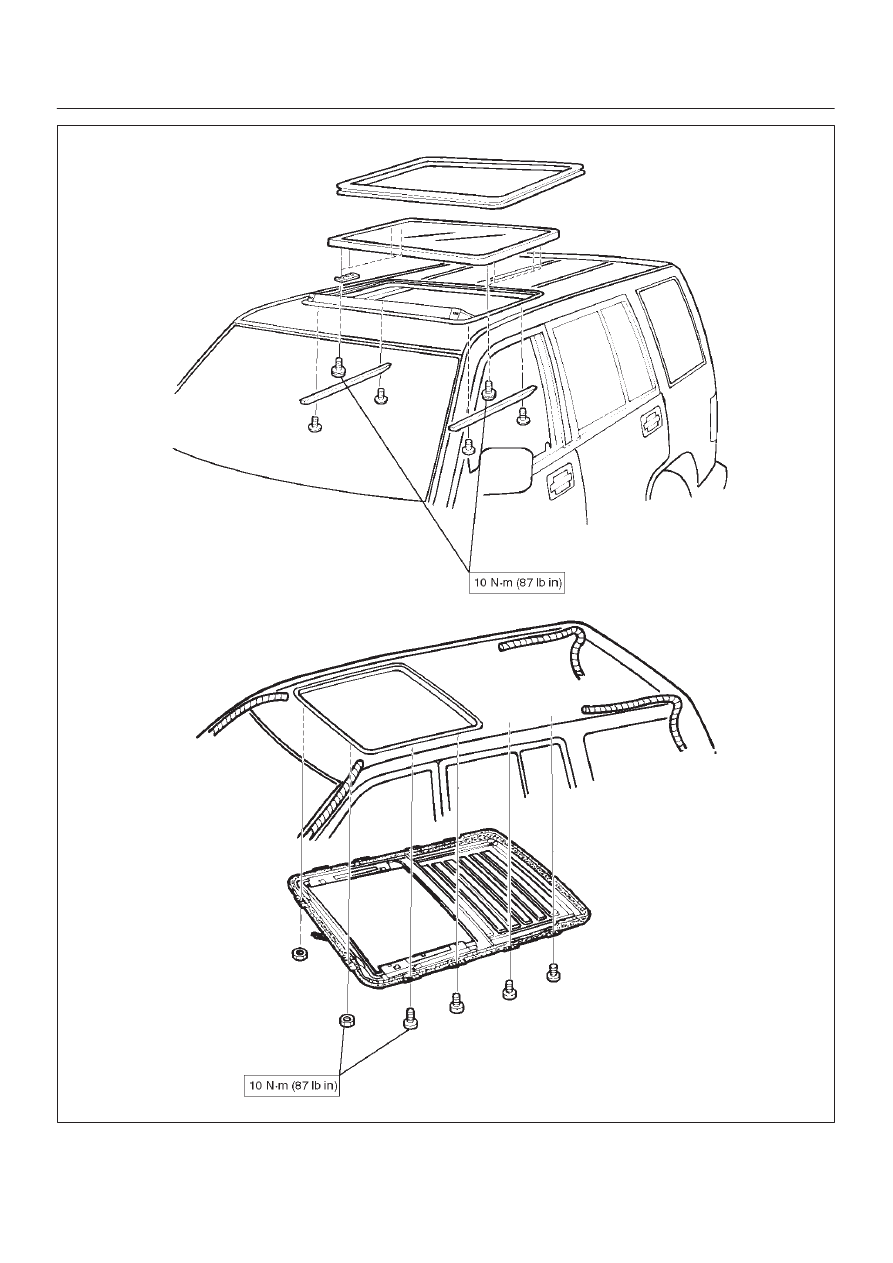
8F–106 BODY STRUCTURE

E10RS010

8F–107

BODY STRUCTURE

Special Tools

ILLUSTRATION

TOOL NO.

TOOL NAME

J–34355

Spare Tire Carrier Nut

Wrench

SEATS

8G–1

TROOPER

BODY AND ACCESSORIES

SEATS

CONTENTS

Service Precaution

8G–1

. . . . . . . . . . . . . . . . . . . . . . 

Front Seat Assembly

8G–2

. . . . . . . . . . . . . . . . . . . . 

Front Seat Assembly and Associated Parts

8G–2

Removal

8G–2

. . . . . . . . . . . . . . . . . . . . . . . . . . . . . 

Installation

8G–2

. . . . . . . . . . . . . . . . . . . . . . . . . . . . 

Disassembled View

8G–3

. . . . . . . . . . . . . . . . . . . . 

Disassembly

8G–4

. . . . . . . . . . . . . . . . . . . . . . . . . . 

Reassembly

8G–5

. . . . . . . . . . . . . . . . . . . . . . . . . . 

Power Seat Assembly

8G–6

. . . . . . . . . . . . . . . . . . . 

General Description

8G–6

. . . . . . . . . . . . . . . . . . . . . 

Disassembled View

8G–6

. . . . . . . . . . . . . . . . . . . . 

Disassembly

8G–7

. . . . . . . . . . . . . . . . . . . . . . . . . . 

Reassembly

8G–9

. . . . . . . . . . . . . . . . . . . . . . . . . . 

Power Seat Switch

8G–9

. . . . . . . . . . . . . . . . . . . . . . 

Removal

8G–9

. . . . . . . . . . . . . . . . . . . . . . . . . . . . . 

Installation

8G–9

. . . . . . . . . . . . . . . . . . . . . . . . . . . . 

Front Tilt Motor / Rear Tilt Motor / Slide Motor
 / Recliner Motor

8G–10

. . . . . . . . . . . . . . . . . . . . . . . . 

Parts Location

8G–10

. . . . . . . . . . . . . . . . . . . . . . . . 

Removal and Installation

8G–10

. . . . . . . . . . . . . . . 

Seat Heater System

8G–11

. . . . . . . . . . . . . . . . . . . . . 

General Description

8G–11

. . . . . . . . . . . . . . . . . . . . . 

Seat Heater Switch Removal and
 Installation

8G–11

. . . . . . . . . . . . . . . . . . . . . . . . . . . 

Heat Unit Parts Location

8G–11

. . . . . . . . . . . . . . . . 

Heat Unit Removal and Installation

8G–11

. . . . . . 

Rear Seat Assembly

8G–12

. . . . . . . . . . . . . . . . . . . . . 

Rear Seat Assembly and Associated Parts

8G–12

Removal

8G–12

. . . . . . . . . . . . . . . . . . . . . . . . . . . . . 

Installation

8G–12

. . . . . . . . . . . . . . . . . . . . . . . . . . . . 

Disassembled View (Split Type)

8G–13

. . . . . . . . . 

Disassembly (Split Type)

8G–14

. . . . . . . . . . . . . . . 

Reassembly (Split Type)

8G–15

. . . . . . . . . . . . . . . . 

Disassembled View (Bench Type)

8G–16

. . . . . . . 

Disassembly (Bench Type)

8G–17

. . . . . . . . . . . . . 

Reassembly (Bench Type)

8G–18

. . . . . . . . . . . . . . 

Main Data and Specifications

8G–18

. . . . . . . . . . . . . 

Service Precaution

WARNING: THIS VEHICLE HAS A SUPPLEMENTAL
RESTRAINT SYSTEM (SRS). REFER TO THE SRS
COMPONENT AND WIRING LOCATION VIEW IN
ORDER TO DETERMINE WHETHER YOU ARE
PERFORMING SERVICE ON OR NEAR THE SRS
COMPONENTS OR THE SRS WIRING. WHEN YOU
ARE PERFORMING SERVICE ON OR NEAR THE SRS
COMPONENTS OR THE SRS WIRING, REFER TO
THE SRS SERVICE INFORMATION. FAILURE TO
FOLLOW WARNINGS COULD RESULT IN POSSIBLE
AIR BAG DEPLOYMENT, PERSONAL INJURY, OR
OTHERWISE UNNEEDED SRS SYSTEM REPAIRS.

CAUTION: Always use the correct fastener in the
proper location. When you replace a fastener, use
ONLY the exact part number for that application.
ISUZU will call out those fasteners that require a
replacement after removal. ISUZU will also call out
the fasteners that require thread lockers or thread
sealant. UNLESS OTHERWISE SPECIFIED, do not
use supplemental coatings (Paints, greases, or other
corrosion inhibitors) on threaded fasteners or
fastener joint interfaces. Generally, such coatings
adversely affect the fastener torque and the joint
clamping force, and may damage the fastener. When
you install fasteners, use the correct tightening
sequence and specifications. Following these
instructions can help you avoid damage to parts and
systems.

SECTION

8G–2

SEATS

Front Seat Assembly

Front Seat Assembly and Associated Parts

750R200027

Legend

(1) Rear Cover
(2) Front Seat Assembly
(3) Seat Belt Warning Connector

(4) Door Sill Plate
(5) Riser Cover
(6) Front Cover

Removal

1. Disconnect the battery ground cable.
2. Remove the front cover.
3. Remove the rear cover.

D

Remove the cover fixing screw from the rear inner
cover, if this model is equipped with the power
seats.

4. Remove the door sill plate.
5. Remove the rear seat foot rest.

D

Refer to the Rear Seat Foot Rest in this section.

6. Remove the riser cover.
7. Remove the seat belt warning connector (Driver’s

side only).

8. Remove the front seat assembly.

D

Disconnect the power seat connector, if this model
is equipped with the power seats.

Installation

To install, follow the removal steps in the reverse order,
noting the following points:


Content   ..  1012  1013  1014  1015   ..