Isuzu Amigo / Axiom / Trooper / Rodeo / VehiCross. Manual - part 35


  Index      Isuzu     Isuzu Amigo / Axiom / Trooper / Rodeo / VehiCross - service repair manual 1999-2002 year


Search            


Content   ..  33  34  35  36   ..


Isuzu Amigo / Axiom / Trooper / Rodeo / VehiCross. Manual - part 35


HEATING, VENTILATION AND AIR CONDITIONING (HVAC) 1A–111
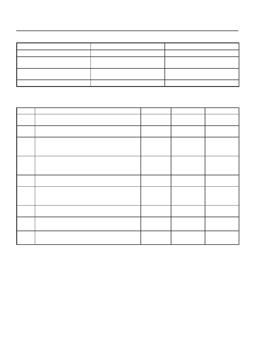
Condition

Possible cause

Correction

The fan dose not rotate at all

Refer to 

Chart A

The fan dose not rotate in the
MAX–HI mode

Refer to 

Chart B

The fan dose not rotate in any mode
other than MAX–HI

Refer to 

Chart C

The fan dose not stop

Refer to 

Chart D

Chart A: Fan Does Not Rotate At All 

Step

Action

Value(s)

Yes

No

1

Are the fuse No.F–5, F–6 and No.F–7 normal?

Go to 

Step 2

Replace the

fuse

2

Are the relay No.X–1 and No.C–35 normal?

Go to 

Step 3

Replace the

relay

3

Turn on the ignition switch (the engine is run).

Is the battery voltage applied between the harness side
connector terminal No.C36–1 and ground?

Go to 

Step 5

Go to 

Step 4

4

Repair an open circuit between terminal No.C36–1 and
No.F–5 and F–6 fuse.

Is the action complete?

Go to 

Step 3

5

Is there continuity between the harness side connector
terminal No.C36–2 and ground (No.C–10)?

Go to 

Step 7

Go to 

Step 6

6

Repair an open circuit between terminal No.C36–2 and
ground.

Is the action complete?

7

Is the battery voltage applied between the harness side
connector terminal No.C36–2 and No.C36–1?

Go to 

Step 8

Go to 

Step 9

8

Replace the blower motor.

Is the action complete?

Verify repair

9

Refer to 

chart B and C.

Is the action complete?

Verify repair

1A–112 HEATING, VENTILATION AND AIR CONDITIONING (HVAC)

Chart B: Fan Does Not Rotate in MAX HI Mode 

Step

Action

Value(s)

Yes

No

1

Is the MAX-HI relay (C–35) normal?

Go to 

Step 2

Replace the

relay

2

1. Turn on the ignition switch (the engine is run).
2. Set the fan switch to the MAX-HI.

Is there continuity between the harness side connector
terminal No.C36–2 and No.C35–5?

Go to 

Step 4

Go to 

Step 3

3

Repair an open circuit between terminal No.C36–2 and
No.C35–5.

Is the action complete?

Go to 

Step 3

4

Is there continuity between the harness side connector
terminal No.C35–1 and ground (No.C–10)?

Go to 

Step 6

Go to 

Step 5

5

Repair an open circuit between terminal No.C35–1 and
ground (No.C–10).

Is the action complete?

Go to 

Step 4

6

Is the battery voltage applied between the harness side
connector terminal No.C35–2 and ground?

Go to 

Step 8

Go to 

Step 7

7

Repair an open circuit between terminal No.C35–2 and
No.F–7 fuse.

Is the action complete?

Go to 

Step 6

8

Is the battery voltage applied between the harness side
connector terminal No.I19–2 and ground?

Go to 

Step 10

Go to 

Step 9

9

Repair an open circuit between terminal No.C35–4 and
No.I19–2.

Is the action complete?

Verify repair

10

Replace the auto air conditioner control unit.

Is the action complete?

Verify repair

HEATING, VENTILATION AND AIR CONDITIONING (HVAC) 1A–113

Chart C: Fan Does Not Rotate In Any Mode Other Than MAX HI 

Step

Action

Value(s)

Yes

No

1

Is the power transistor performance normal? (Refer to
the 

later section on “individual inspection”)

Go to 

Step 2

Replace the

power

transistor

2

Is there continuity between the harness side connector
terminal No.C36–2 and No.C34–1, No.C36–2 and
No.I20–17?

Go to 

Step 4

Go to 

Step 3

3

Repair an open circuit between terminal.

No.C36–2 and C34–1
No.C36–2 and I20–17

Go to 

Step 2

4

Is there continuity between the harness side connector
terminal No.C34–3 and ground (No.C–10)?

Go to 

Step 6

Go to 

Step 5

5

Repair an open circuit between terminal No.C34–3 and
ground.

Is the action complete?

Go to 

Step 4

6

Is there continuity between the harness side connector
terminal No.C34–2 and No.I20–19?

Go to 

Step 8

Go to 

Step 7

7

Repair an open circuit between terminal No.C34–2 and
No.I20–19.

Is the action complete?

Go to 

Step 6

8

Replace the auto air conditioner control unit.

Is the action complete?

Verify repair

1A–114 HEATING, VENTILATION AND AIR CONDITIONING (HVAC)

Chart D: Fan Does Not Stop 

Step

Action

Value(s)

Yes

No

1

1. Disconnect the max high relay, the power transistor

connector C–34 and the auto A/C control unit
connector I–20.

2. Turn on the ignition switch.

Does the blower motor stop?

Go to 

Step 3

Go to 

Step 2

2

Repair a short circuit between connector No.C36–2
and No.C35–5, No.C36–2 and No.C34–1, or
No.C36–2 and I20–17.

Is the action complete?

Verify repair

3

Is the max high relay normal? (Refer to the 

later section

on “individual inspection”.)

Go to 

Step 4

Replace the

relay

4

Reinstall the max high relay.

Does the blower motor start operating?

Go to 

Step 6

Go to 

Step 5

5

Repair a short circuit between connector No.C35–4
and No.I19–2.

Is the action complete?

Go to 

Step 4

6

Is the power transistor normal? (Refer to the 

later

section on “individual inspection”.)

Go to 

Step 7

Replace the

power

transistor

7

Reinstall the power transistor.

Does the blower motor start operating?

Replace the

auto A/C

control unit


Content   ..  33  34  35  36   ..