Isuzu Amigo / Axiom / Trooper / Rodeo / VehiCross. Manual - part 11


  Index      Isuzu     Isuzu Amigo / Axiom / Trooper / Rodeo / VehiCross - service repair manual 1999-2002 year


Search            


Content   ..  9  10  11  12   ..


Isuzu Amigo / Axiom / Trooper / Rodeo / VehiCross. Manual - part 11


HEATING, VENTILATION AND AIR CONDITIONING (HVAC) 1A–15
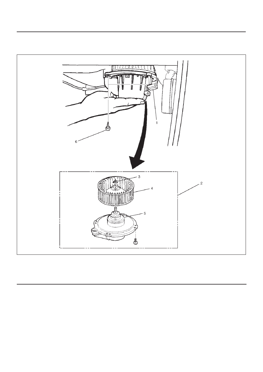
Blower Motor

Blower Motor and Associated Parts

873RS004

Legend

(1) Blower Motor Connector
(2) Blower Motor Assembly
(3) Clip

(4) Fan
(5) Blower Motor
(6) Attaching Screw

Removal

1. Disconnect the battery ground cable.
2. Remove blower motor connector.
3. Remove attaching screw.
4. Remove blower motor assembly.
5. Remove clip.
6. Remove fan.
7. Remove blower motor.

Installation

To install, follow the removal steps in the reverse order.

1A–16 HEATING, VENTILATION AND AIR CONDITIONING (HVAC)

Rear Heater Duct, Defroster Nozzle and Ventilation Duct

Rear Heater Duct, Defroster Nozzle, Ventilation Duct and Associated Parts

840R200009

Legend

(1) Defroster Nozzle
(2) Cross Beam Assembly
(3) Center Ventilation Duct and Side Defroster

Duct

(4) Instrument Panel Bracket W/Suspension

Control Unit

(5) Instrument Panel Assembly
(6) Rear Heater Duct
(7) Ventilation Lower Duct

Removal

1. Disconnect the battery ground cable.
2. Remove instrument panel assembly.

D

Refer to 

Instrument Panel Assembly in Body and

Accessories section.

3. Remove center ventilation duct and side defroster

duct.

D

Remove 5 screws.

4. Remove instrument panel brackets w/suspension

control unit.

D

Refer to 

Cross Beam Assembly in Body and

Accessories section.

5. Remove cross beam assembly.

D

Refer to 

Cross Beam Assembly in Body and

Accessories section.

6. Remove ventilation lower duct.

HEATING, VENTILATION AND AIR CONDITIONING (HVAC) 1A–17

7. Remove rear heater duct.

D

Remove foot rest carpet and 3 clips.

8. Remove defroster nozzle.

Installation

To install, follow the removal steps in the reverse order,
noting the following point:

1. Connect each duct and nozzle securely leaving no

clearance between them and making no improper
matching.

1A–18 HEATING, VENTILATION AND AIR CONDITIONING (HVAC)

Air Conditioning System

General Description

Air Conditioning Refrigerant Cycle Construction

C01RY00013

Legend

(1) Duct Sensor
(2) Evaporator Core
(3) Evaporator Assembly
(4) Temperature Sensor
(5) Blower Motor
(6) Expansion Valve
(7) Pressure Switch
(8) Receiver/Drier

(9) Condenser

(10) Compressor

(11) Magnetic Clutch

(12) Mode (HEAT) Control Door
(13) Temp. Control Door (Air Mix Door)
(14) Heater Core
(15) Mode (VENT) Control Door
(16) Heater Unit
(17) Mode (DEF) Control Door

The refrigeration cycle includes the following four
processes as the refrigerant changes repeatedly from
liquid to gas and back to liquid while circulating.


Content   ..  9  10  11  12   ..