Isuzu N-Series. Manual - part 566


  Index      Isuzu     Isuzu N-Series - service repair manual


Search            


Content   ..  564  565  566  567   ..


Isuzu N-Series. Manual - part 566


GENERAL ENGINE MECHANICAL 6A-21

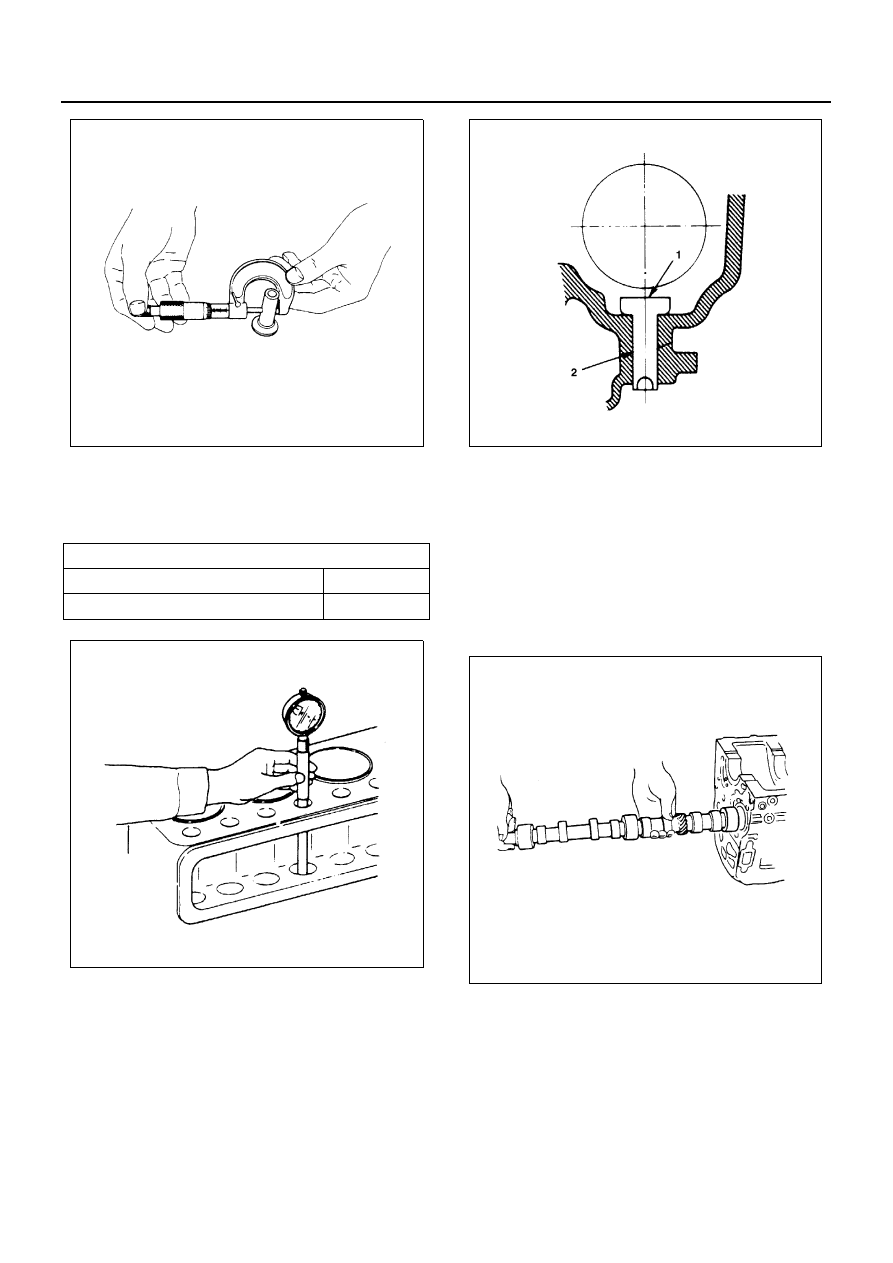
2. Measure the inside diameter tappet on the cylinder

block and calculate the clearance.
If the clearance exceeds the limit, replace tappet
or/and cylinder block.

Reassembly

1. Tappet

1) Apply a coat of engine oil to the tappet (1) and

the cylinder body tappet insert holes (2).

2) Locate the position mark applies at disassem-

bly (if the tappet is to be reused).

Notice:
The tappet must be installed before the camshaft.

2. Camshaft

1) Apply a coat of engine oil to the camshaft and

the camshaft bearings.

2) Install the camshaft to the cylinder body.

Take care not damage the camshaft bearings.

3. Camshaft Timing Pulley Center (Belt Drive Model)

• Apply engine oil to the oil seal lip portion of the

oil seal retainer.

• Apply the recommended liquid gasket or its

equivalent to the retainer.

• Install the oil seal retainer to the cylinder body.
• Tighten the retainer bolts to the specified

torque.

Tappet and Cylinder Body Clearance

mm (in)

Standard

Limit

0.03 (0.001)

0.10 (0.004)

N6A3103E

N6A3104E

N6A3105E

N6A3106E

6A-22 GENERAL ENGINE MECHANICAL

Tighten:
Oil Seal Retainer Bolt to 19 N

⋅m (1.9 kg⋅m/14 lb⋅ft)

• Align the camshaft timing pulley center with the

camshaft key.

• Tighten the timing pulley bolts to the specified

torque.

Tighten:
Timing Pulley Bolt to 8 N

⋅m (0.8 kg⋅m/69 lb⋅ft)

4. Camshaft Thrust Plate (Gear Drive Model)

Install the thrust plate to the cylinder body and
tighten the thrust plate bolts to specified torque.

Tighten:
Thrust Plate Bolt to 18 N

⋅m (1.8 kg⋅m/13 lb⋅ft)

5. Camshaft Timing Pulley (Belt Drive Model)

• Prevent the camshaft from turning when tight-

ening the timing center bolt.

• Tighten the timing pulley center bolt to the

specified torque.

Tighten:
Center Bolt to 64 N

⋅m (6.5 kg⋅m/47 lb⋅ft)

6. Camshaft Timing Gear (Gear Drive Model)

1) Install the camshaft timing gear to the cam-

shaft.
The timing gear mark (“Y — Y”) must be facing
outward.

2) Tighten the timing gear to the specified torque

Legend

1. Retainer

Legend

1. Timing pulley center
2. Timing pulley

N6A3107E

N6A3108E

Legend

1. Lock bolt

N6A3109E

N6A3110E

GENERAL ENGINE MECHANICAL 6A-23

Tighten:
Timing Gear Bolt to 64 N

⋅m (6.5 kg⋅m/47 lb⋅ft)

7. Oil Pump Assembly
8. Oil Pan Assembly

Above works refer to “OIL PUMP” Section in this
manual.

9. Cylinder Block Rear Plate

• Tighten cylinder block rear plate fixing bolts to

the specified torque.

Tighten:
Rear Plate Bolt to 82 N

⋅m (8.4 kg⋅m/61 lb⋅ft)

10. Flywheel

• Apply engine oil to fixing bolts.
• Tighten the flywheel bolts to the specified

torque in two steps using the Angular Tighten-
ing Method.
Follow the numerical order shown in the illus-
tration.

Tighten:

• Flywheel Bolt to 

1st Step (Snug torque): 59 N

⋅m (6.0 kg⋅m/43 lb⋅ft)

2nd Step (Final torque): 60

° — 90°

11. Cylinder Head Assembly

1) Hot plug 

• Set the nock ball in the positioning groove on

the cylinder head side according to the order
of the cylinders, and hit it lightly with a plastic
hammer. 

Notice:
After being pressed into the cylinder head, the hot plugs
were provided with surface grinding.
Accordingly, their dimensions are different individually
among them, and take care not confuse the order of the
cylinders.
When replacing the hot plug with new one:
When assembling a new hot plug, set the knock ball in
the positioning groove on the cylinder side and hit it
lightly with a plastic hammer until the hot plug is set in
stably.
With patch attached to the hot plug to prevent it from be-
ing damaged, press it in with a force of 4.5 ~ 5.5 ton ap-
plied.

2) Valve Seat Insert Installation

• Carefully place the attachment (1) (having a

smaller outside diameter than the valve seat
insert) on the valve seat insert (2).

Notice:
The smooth side of the attachment must contact the
valve seat insert.

• Use the bench press (3) to gradually apply

pressure to the attachment and press the
valve seat insert into place.

N6A3111E

N6A3112E

6A-24 GENERAL ENGINE MECHANICAL

Notice:
Do not apply an excessive amount of pressure with the
bench press. Damage to the valve seat insert will result.

Measure the height of the valve guide upper
end from the upper face of the cylinder head.

Notice:
If the valve guide has been removed, both the valve and
the valve guide must be replaced as a set.

3) Spring Lower Seat
4) Valve Stem Oil Seal
5) Valve
6) Valve Spring
7) Split Collar

Above works refer to “VALVE” Section in this
manual.

Valve Guide Upper End Height (H) (Reference)

mm (in)

13 (0.51)

N6A3086E

N6A3067E


Content   ..  564  565  566  567   ..