Isuzu N-Series. Manual - part 51


  Index      Isuzu     Isuzu N-Series - service repair manual


Search            


Content   ..  49  50  51  52   ..


Isuzu N-Series. Manual - part 51


SERVICE INFORMATION 00-35

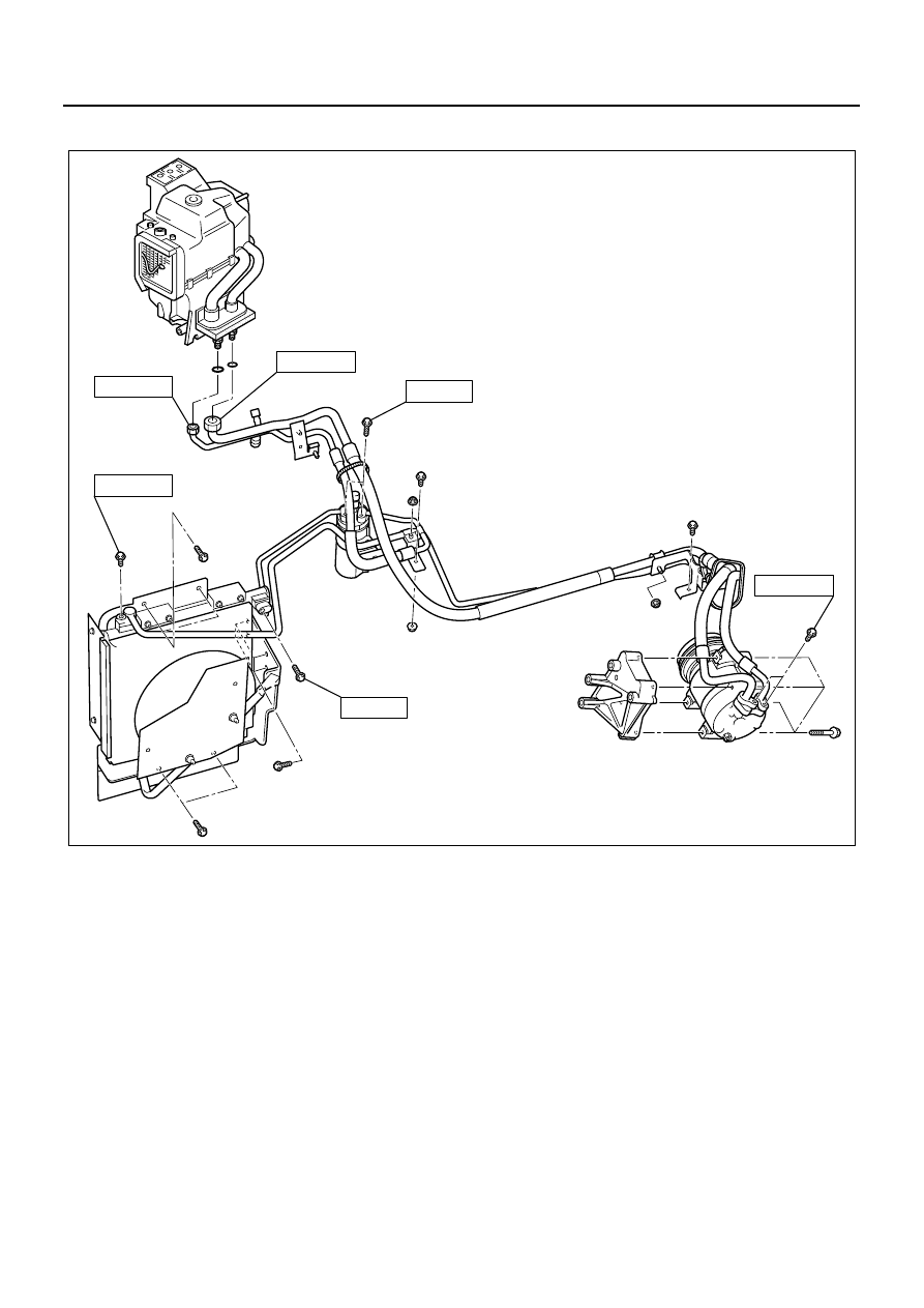
Refrigerant Line Fixing Torque (4HK1-TC Engine Model For Australia)

25 (2.5 / 18)

6 (0.6 / 4)

N.m (kg.m / lb.ft)

6 (0.6 / 4)

15 (1.5 / 11)

15 (1.5 / 11)

15 (1.5 / 11)

N1A0196E

00-36 SERVICE INFORMATION

Drive Plate / Field Coil Fixing Torque

15 (1.5/11)

5 (0.5/44)

N1A0015E

SERVICE INFORMATION 00-37

SPECIAL TOOLS

Illustration

Tool Number / 

Description / Remarks

5-8840-0629-0 (J-39500-

A) / ACR

4

 (115V 60Hz)

5-8840-0630-0 (J-39500-

220A) / ACR

4

 (220-240V 

50/60Hz)

5-8840-0631-0 (J-39500-

220ANZ) / ACR

4

 (220-

240V 50/60Hz Australian 

model)

ACR

4

: R-134a Refriger-

ant Recovery/ Recycling 

/ Recharging / System

5-8840-0117-0 (J-33939) 

/ Drive plate holder

5-8840-0122-0 (J-33944-

A) / Drive plate puller

5-8840-0621-0 (J-33944) 

/ Forcing screw

5-8840-0121-0 (J-33943) 

/ Pulley puller pilot

5-8840-0111-0 (J-8433) / 

Pulley puller

5884006290

5884001170

5884001220

5884006210

5884001210

5884001110

5-8840-0120-0 (J-33942) 

/ Shaft seal remover and 

installer

5-8840-0368-0 (J-34614) 

/ Shaft seal guide

5-8840-0118-0 (J-33940) 

/ Pulley installer

5-8840-0007-0 (J-8092) / 

Drive handle

Illustration

Tool Number / 

Description / Remarks

5884001200

5884003680

5884001180

5884000070

HEATING AND VENTILATION 1A-1

HEATING AND AIR CONDITIONING

SECTION 1A

HEATING AND VENTILATION

Caution:

When fasteners are removed, always reinstall them at the same location from which they were removed. If a fastener
needs to be replaced, use the correct part number fastener for that application. If the correct part number fastener is
not available, a fastener of equal size and strength (or stronger) may be used. 

Fasteners that are not reused, and those requiring thread locking compound, will be called out. The correct torque
values must be used when installing fasteners that require it. If the above conditions are not followed, parts or system
damage could result.

Contents

GENERAL DESCRIPTION ................................... 1A-2

Heater................................................................ 1A-2
Control Lever Assembly .................................... 1A-3
Ventilation.......................................................... 1A-4
Air Select Lever ................................................. 1A-4
Air Source Select Lever..................................... 1A-4
Fan Switch Lever............................................... 1A-4
Temperature Control Lever ............................... 1A-5

ON-VEHICLE SERVICE ....................................... 1A-6

Heater Unit/Heater Core.................................... 1A-6
Heater Temperature Control Link Unit/Air Mix Door .. 1A-8
Heater Mode Control Link Unit/Mode Door ....... 1A-9
Blower Assembly ............................................. 1A-10
Blower Link Unit/Mode Door............................ 1A-13
Blower Motor ................................................... 1A-14
Blower Filter..................................................... 1A-16
Ventilation Grille .............................................. 1A-17
Defroster Nozzle/Ventilation Duct.................... 1A-19
Control Lever Assembly .................................. 1A-20
Control Panel Illumination Bulb ....................... 1A-23
Resistor ........................................................... 1A-24


Content   ..  49  50  51  52   ..