Isuzu engine 4j series. Manual - part 96


  Index      Isuzu     Isuzu engine 4j series - service manual


Search            


Content   ..  94  95  96  97   ..


Isuzu engine 4j series. Manual - part 96


6F – 2  ENGINE EXHAUST
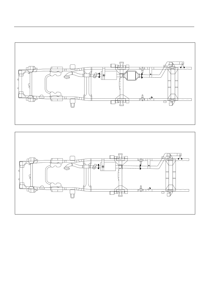
GENERAL DESCRIPTION

When inspecting or replacing exhaust system components,
make sure there is adequate clearance from all points on the
underbody to prevent overheating of the floor pan and possible
damage to the passenger compartment insulation and trim
materials.
Check complete exhaust system and nearby body areas and
rear compartment lid for broken, damaged, missing or
mispositioned parts, open seams, holes, loose connections or
other deterioration which could permit exhaust fumes to seep
into the rear compartment or passenger compartment.  Dust or
water in the rear compartment may be an indication of a
problem in one of these areas.  Any faulty areas should be
corrected immediately.

General Export

501LX002.tif

501LX003.tif

Model ’91/542B (Euro 2)

ENGINE EXHAUST  6F – 3

THREE WAY CATALYTIC CONVERTER

The three way catalytic converter is an emission control
device added to the exhaust system to reduce pollutants
from the exhaust gas stream.

CAUTION:

The catalytic converter requires the use of unleaded
fuel only.

Periodic maintenance of the exhaust system is not
required. If the vehicle is raised for other service, it is
advisable to check the condition of the complete exhaust
system.
A dual bed monolith catalytic converter is used in
combination with three way catalytic converter.
Catalytic Types:

Three way (Reduction/Oxidation) catalyst

The catalyst coating on the three way (reduction)
converter contains platinum and rhodium which lowers the
levels of oxide of nitrogen (NOx) as well as hydrocarbons
(HC) and carbon monoxide (Co).

150LS001.tif

6F – 4  ENGINE EXHAUST

ON-VEHICLE SERVICE

Rattles and noise vibrations in the exhaust system are usually
caused by misalignment of parts.  When aligning the system,
leave all bolts or nuts loose until all parts are properly aligned;
then tighten, working from front to rear.

1. Check connections for looseness or damage,

especially for exhaust gas leakage.

2. Check clamps and rubbers for weakness, cracks or

damage.

3. If any part of the converter heat shield is damaged or

dented to the extent that it contacts the catalyst, repair
or replace.

4. Check for dents or damage and for any holes or

cracks caused by corrosion.

FRONT EXHAUST PIPE

REMOVAL

Preparation:

Battery ground cable

1. Exhaust manifold fixing nuts.

Remove two fixing nuts from exhaust manifold and
front pipe.

2. Front exhaust pipe mounting bracket fixing bolt and

nut.

3. Front exhaust pipe fixing bolts and nuts.

Remove two bolts fixed from front pipe and center
pipe.

4. Front exhaust pipe.

Take out the exhaust pipe to another side.

6F-6-1.tif

6F-6-2.tif

ENGINE EXHAUST  6F – 5

INSTALLATION

4. Front exhaust pipe.

3. Front exhaust pipe fixing bolts and nuts.

Tighten the fixing nuts to the specified torque

N∙m (kg∙m/lb∙ft)


50 (5.1/37)


2. Front exhaust pipe mounting bracket fixing bolt and nut.

Tighten the fixing bolt to the specified torque

N∙m (kg∙m/lb∙ft)


40 (4.1/30)


1. Exhaust manifold fixing nuts

Tighten the fixing nuts to the specified torque

N∙m (kg∙m/lb∙ft)


69 (7/51)


Connect battery ground cable.

After assembling each part, start the engine to check
for any leakage of gas at each connection.

Exhaust Brake Unit

INSPECTION

Operational inspection

With the engine idling, operate the exhaust brake to
check for the sound of the valve hitting against the
stopper.

Unit inspection

Check to see if the exhaust valve opens and closes
smoothly when the power chamber is
applied with a negative pressure (400 mmHg - 700
mmHg) by the vacuum pump.

Check to see if the clearance between the valve and
the body is in the range of 0.1 mm - 0.2 mm (the
minimum of 0.1 mm) on an average of the points “A”
and “B” when the power chamber is applied with a
negative pressure (650 mmHg - 700 mmHg) by the
vacuum pump.
When the clearance is outside this range, adjust the
clearance with the adjust bolt.

6F-7-1.tif

6F-5-2.tif

6F-5-3.tif


Content   ..  94  95  96  97   ..