Isuzu engine 4j series. Manual - part 85


  Index      Isuzu     Isuzu engine 4j series - service manual


Search            


Content   ..  83  84  85  86   ..


Isuzu engine 4j series. Manual - part 85


6D2 – 10  STARTING SYSTEM

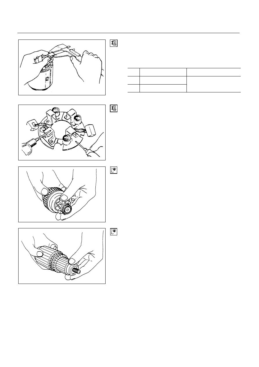
BRUSH AND BRUSH HOLDER

Measure the brush length and replace if it is worn beyond
the service limit.
Brush length

mm (in.)

kw

Standard

Limit

2.2

14.5 (0.57)

2.0

16 (0.63)

10 (0.39)

Brush holder insulation test

Using a circuit tester, check the brush holder insulation.
Touch one probe to the holder plate and the other to the
positive brush holder.  There should be no continuity.

OVERRUNNING CLUTCH

Inspect the teeth of pinion for wear and damage.
Replace if it damaged.
Rotate the pinion in direction of rotation (clockwise).
It should rotate smoothly.  But in opposite direction, it
should be locked.

BEARING

Check the bearings for wear and damage.  If the bearings
are noisy during operation, they should be replaceds.

6D2-10-1.tif

6D2-10-2.tif

6D2-10-3.tif

6D2-10-4.tif

STARTING SYSTEM  6D2 – 11

REASSEMBLY

To install, follow the removal steps in the reverse order,
noting the following points:

Magnetic Switch

Idle Gear

Clutch assembly

Housing

1) Install the clutch asm to the magnetic switch.
2) Install the idle gear and housing.

Note:

Do not fail to assemble the steel ball and the spring
between the clutch and magnetic switch.

Assemble the roller to the idle gear in advance.

6D2-11-1.tif

6D2 – 12  STARTING SYSTEM

MAGNETIC SWITCH

Temporarily connect the solenoid switch between the
clutch and the housing and run the following tests.
Complete each test within three to five seconds.

1. Pull-in test

Connect the battery negative terminal with the solenoid
switch body and the M terminal.  When current is applied
to the 50 terminal from the battery positive terminal, the
pinion should flutter.

2. Hold-in test

Disconnect the lead at the M terminal.  The pinion should
continue to flutter.

3. Return test

Connect the battery negative terminal to the 50 terminal
and the body.  Connect the battery positive terminal to the
M terminal.  The pinion will flutter.  When the lead to the
50 terminal is disconnected, the pinion should immediately
return to its stationary positions.

4. Current value

Make connections as shown in the illustration, and
measure the current value.

Standard = 120 A or less

Note:

For a battery, be sure to use one fully charged.

For lead wires, use thick ones since a large amount of
current flows through them.

6D2-12-1.tif

6D2-12-2.tif

6D2-12-3.tif

6D2-12-4.tif

CHARGING SYSTEM  6D3 – 1

SECTION 6D3

CHARGING SYSTEM

CONTENTS

PAGE

General Description....................................................................................................... 6D3 - 1

Diagnosis........................................................................................................................ 6D3 - 4

On-Vehicle Service ........................................................................................................ 6D3 - 5

Unit Repair...................................................................................................................... 6D3 - 9

GENERAL DESCRIPTION

The charging system is the IC integral regulator
charging system and its main components are
connected as shown in Figure.
The regulator is a solid state type and it is mounted
along with the brush holder assembly inside the
generator installed on the rear end cover.

The generator does not require particular maintenance
such as voltage adjustment.  The rectifier connected to
the stators coil has nine diodes to transform A.C.
voltage into D.C. voltage.  This D.C. voltage is
connected to the output terminal of generator.


Content   ..  83  84  85  86   ..