Isuzu engine 4j series. Manual - part 32


  Index      Isuzu     Isuzu engine 4j series - service manual


Search            


Content   ..  30  31  32  33   ..


Isuzu engine 4j series. Manual - part 32


6A – 64

  GENERAL ENGINE MECHANICAL

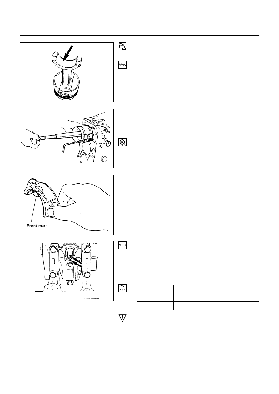
12) Carefully wipe any oil or other foreign material from

connect rod bearing back face and the connecting rod
bearing fitting surface.

13) Apply a coat of engine oil to the upper bearing

surfaces.
Apply a coat of engine oil to the cylinder wall.

14) Position the piston head from mark so that it is facing

the front of engine.
Use the piston ring compressor to compress the piston
rings.
Piston Ring Compressor: 5-8840-9018-0 (J-8037)

15) Use a hammer grip to push the piston in until the

connecting rod makes contact with the crankpin.
At the same time, rotate the crankshaft until the
crankpin is at BDC.

16) Position the bearing cap front mark so that it is facing

the front of the engine.

17) Install the connecting rod bearing caps.

Align the bearing cap cylinder number marks and the
connecting rod cylinder number marks.

18) Apply a coat of engine oil to the threads and setting

faces of each connecting rod cap bolt.

19) Tighten the connecting rod bearing cap bolts to the

specified torque in two steps using the Angular
Tightening Method.

Connecting Rod Bearing Cap Bolt
Torque

N∙m (kg∙m/lb∙ft)

1st Step

2nd Step

4JG2

29 (3.0/22)

45° - 75°

4JB1/4JB1TC

83 (8.5/61)

NOTE

Check to see that the crankshaft turns smoothly by
rotating it manually.

6A-64-1.tif

6A-64-3.tif

6A-64-2.tif

6A-64-4.tif

GENERAL ENGINE MECHANICAL   6A – 65

7. Piston Cooling Oil Pipe

1) Fix the oil jet pipes with knock pins on the cylinder

block.

2) Install the oil pipe for piston cooling in the cylinder

block, tightening a relief valve 

!

 and four joint bolts 

"

to the specified torque.

Oil pipe fixing bolts

N∙m (kg∙m/lb∙ft)

M8: 19 (1.9/14)

M6: 8 (0.8/69 lb∙in.)

Relief valve fixing bolt

N∙m (kg∙m/lb∙ft)


29 (3.0/22)


CAUTION:

After installed the piston assembly. Check and see
that there is appropriate clearance between pistons
and oil jet pipes by rotating crankshaft slowly.

6. Oil Pump Assembly

Above works refer to “OIL PUMP” Section in this manual.

5a. Timing Pulley Housing

5. Timing Gear Housing

4. Front Oil Seal (Belt Drive Model)

3a. Timing Belt and Pulley

6) Camshaft Timing Pulley
5) Timing Belt
4) Flange: Camshaft Pulley
3) Timing Pulley Lower Cover
2) Timing Pulley Upper Cover
1) Crankshaft Damper Pulley

3. Timing Gear (Gear Drive Model)

11) Crankshaft Gear
10) Crankshaft Timing Gear

9) Idle Gear
8) Idler Gear "B" and Shaft
7) Injection Pump
6) Timing Gear Oil Pipe
5) Timing Gear Case Cover
4) Crankshaft Damper Pulley
3) Cooling Fan Assembly
2) AC Generator, Power Steering Pump Drive Belt
1) Fan Shroud

Above works refer to “CRANKSHAFT” Section in this
manual.

6A-65-1.tif

6A – 66

  GENERAL ENGINE MECHANICAL

2. Oil Pan Assembly

Above works refer to “OIL PUMP” Section in this
manual.

1. Cylinder Head Assembly and Gasket

!

Cylinder head gasket is determined by the piston
head projection from the cylinder body upper
surface, in order to improve engine performance.
Three types of gasket are provided by the
difference of thickness. Select the adequate one
out of three grades of gasket, according to the
following procedure.
Before measurement, clear off carbon from the
piston head and cylinder body surface and also
clean the place where a gasket was installed.

Piston Head Projection Measurement Point

"

Use a dial indicator to measure the piston
projection amount.

#

Refer to the illustration for the piston head
projection measuring positions.
All measuring positions should be as close as
possible to the cylinder liner.

$

Measure the points 

! " # $

 and obtain two

difference 

!

 - 

"

 and 

#

 - 

$

 on each cylinder.

Calculate the average value of the piston head
projection on each cylinder.

%

Obtain the maximum value in the four cylinders.

&

Determine the gasket grade required to the
maximum value described above in accordance
with the following table.

4JB1 / 4JB1T / 4JB1TC
Cylinder Head Gasket Thickness

mm (in)

Gasket Grade

Mark

Piston

Projection

Gasket

Thickness

(Reference)

A

0.758-0.813

(0.030-0.032)

1.60 (0.0630)

B

0.813-0.859

(0.032-0.034)

1.65 (0.0650)

C

0.859-0.914

(0.034-0.036)

1.70(0.0670)

NOTE:

The difference between the highest measured piston
head projection and the lowest measured piston head
projection must not exceed 1.0mm (0.039 in).

6A-66-1.tif

6A-66-2.tif

6A-66-3.tif

GENERAL ENGINE MECHANICAL   6A – 67

4JG2  Cylinder Head Gasket Thickness

mm (in)

Grade

mark

Average Piston

projection

Gasket

thickness

A

0. 658-0.713

(0.0259-0.0281)

1.60

(0.0630)

B

0.713-0.759

(0.0281-0.0299)

1.65

(0.0650)

C

0.759-0.814

(0.0299-0.0320)

1.70

(0.0670)

NOTE:

The difference between the highest measured piston
head projection and the lowest measured piston head
projection must not exceed 1.0mm (0.039 in).

Cylinder Head Assembly

!

Install the dowel in cylinder block.

"

Install the cylinder head gasket with top mark up.

#

Clean up cylinder head lower surface and cylinder
body upper surface.

$

Install the cylinder head as softly.

%

Apply molybdenum disulfide grease to screw and seat
of cylinder head bolts.

&

Tighten the cylinder head bolts to the specific torque in
three step following the numerical and shown in the
illustration.

Cylinder Head Bolts Torque

N∙m (kg∙m/lb∙ft)

1st Step

2nd Step

3rd Step

49 (5.0/36)

60° - 75°

60° - 75°

Push Rod

Apply engine oil to push rod and into the cylinder head.

Rocker Arm Shaft Assembly

!

Loosen all adjusting screws.

"

Position the rocker arm shaft with the large oil hole
(4ø) facing the front of the engine.

6A-67-1.tif

6A-67-2.tif

6A-67-3.tif


Content   ..  30  31  32  33   ..