Isuzu KB P190. Manual - part 981


  Index      Isuzu     Isuzu KB P190 - service repair manual 2007 year


Search            


Content   ..  979  980  981  982   ..


Isuzu KB P190. Manual - part 981


Automatic Transmission – 4L60E – On-vehicle Servicing 

Page 7C4–11 

3.2 

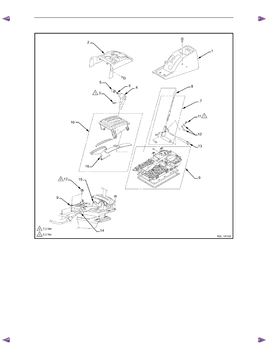
Shift Selector Assembly 


Figure 7C4 – 6 

Legend 

1 Rear 

Console 

2 Front 

Console 

Screw – Knob 

4 Knob 

Button – Knob 

Spring – Knob 

7 Selector 

Lever 

Assembly 

8 Sleeve 

9 Base 

Plate 

10 

Upper Housing Assembly 

11 

Screw – Spring Plate 

12 Spring 

Plate 

13 Grooved 

Pin 

14 Selector 

Cable 

15 

Selector Lever Linkage 

16 Lamp 

17 

Nut – Base Plate 

Remove 

Remove the front and rear console, refer to 10 Cab. 

Position the transmission selector lever to the N position. 

Remove the screw (3), two places, attaching the selector lever knob (4), refer to Figure 7C4 – 6. 

Automatic Transmission – 4L60E – On-vehicle Servicing 

Page 7C4–12 

Remove the knob together with the button (5) and spring (6) from the selector lever assembly (7). 

Turn the sleeve (8) counter clockwise to remove it, make note of the number of turns required to free it. 

Remove the harness connectors from the base plate (9). 

Remove the upper housing (10) which is held in place by four latched fasteners. 

Remove the attaching screw (11) and spring plate (12). 

Remove the grooved pin (13). 

10 

Using a small flat blade screwdriver, gently prise the upper end of the selector cable (14) from the pin on the 
selector lever linkage (15). 

11 

Remove the selector lever assembly by pressing the rod down (lever in the N position). 

12 

If required, remove the lamp (16) from its socket by aligning the groove in the socket and the protruding part of the 
lamp. 

13 

If required, remove the nut (17), four places, and the shift selector base plate. 

Reinstall 

Apply MULTEMP No 2 grease, or equivalent to the selector lever as indicated in Figure 7C4 – 7. 


Figure 7C4 – 7 

If required, install the shift selector base plate (9) and tighten the nut (17), four places, to the correct torque 
specification, refer to Figure 7C4 – 6. 

Shift selector base plate attaching nut 
torque specification ..............................................7.0 Nm 

Install the selector lever assembly (7) to the base plate: 

insert and secure the rod, 

insert the paw led end of the selector lever linkage (15) into the base plate hole, 

attach the end of the selector cable to the pin on the selector lever linkage, 

Automatic Transmission – 4L60E – On-vehicle Servicing 

Page 7C4–13 

Install the grooved pin (13) in the selector lever. 

Insert the grooved pin in the base plate détente groove 
until it touches the front wall. The selector lever is in 
the N position. 

Figure 7C4 – 8 

Install the spring plate (12) and tighten the screw (11) to the correct torque specification, refer to Figure 7C4 – 6. 

Spring plate attaching screw 
torque specification ..............................................2.0 Nm 

With the selector lever knob temporarily installed, ensure the grooved pin of the selector lever moves smoothly in 
the base plate détente groove. 

Temporarily install the sleeve (8). 

If previously removed, install the lamp (16) by aligning the groove in the socket and the protruding part of the lamp 
and rotate the lamp 90 degrees clockwise. 

Attach the harness connectors to the base plate. 

10 

Position the transmission selector lever to the P position. 

11 

Install the sleeve (8) by rotating it clockwise the same number of turns as noted on removal. 

12 

Fit the upper housing (10) over the selector lever assembly, do not secure at this stage. 

13 

Install the knob (4) together with the button (5) and spring (6) to the selector lever assembly. 

14 

Adjust the clearance (2) between the base plate 
détente groove and the grooved pin by moving the 
selector lever knob sleeve (1). 

Base plate détente groove and  
grooved pin clearance................................ 0.2 – 1.0 mm 


Figure 7C4 – 9 

15 

Install the screw (3), two places, attaching the knob and tighten to the correct torque specification, refer to  
Figure 7C4 – 6. 

Automatic Transmission – 4L60E – On-vehicle Servicing 

Page 7C4–14 

Selector lever knob attaching screw 
torque specification ..............................................2.0 Nm 

16 

Secure the upper housing (10) to the base plate with the four latched fasteners. 

17 

Install the front and rear console, refer to 10 Cab. 

3.3 

Selector Cable Assembly 


Figure 7C4 – 10 

Legend 

1 Selector 

Cable 

2 Selector 

Lever 

Linkage 

Retaining Pawl – Selector Cable 

Shift Selector Base Plate 

Screw – Heat Shield 

Screw – Heat Shield 

7 Heat 

Shield 

External Manual Shaft Linkage 

9 Bracket 

10 Bolt 

– 

Bracket 


Content   ..  979  980  981  982   ..