Index Isuzu Isuzu KB P190 - service repair manual 2007 year
Search
Content .. 918 919 920 921 ..
Isuzu KB P190. Manual - part 920
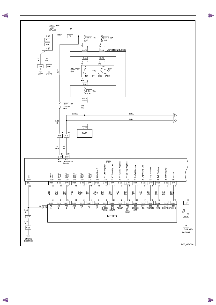
Powertrain Interface Module – V6
Page 6E1–19
Figure 6E1 – 14