Isuzu KB P190. Manual - part 917
Powertrain Interface Module – V6
Page 6E1–7
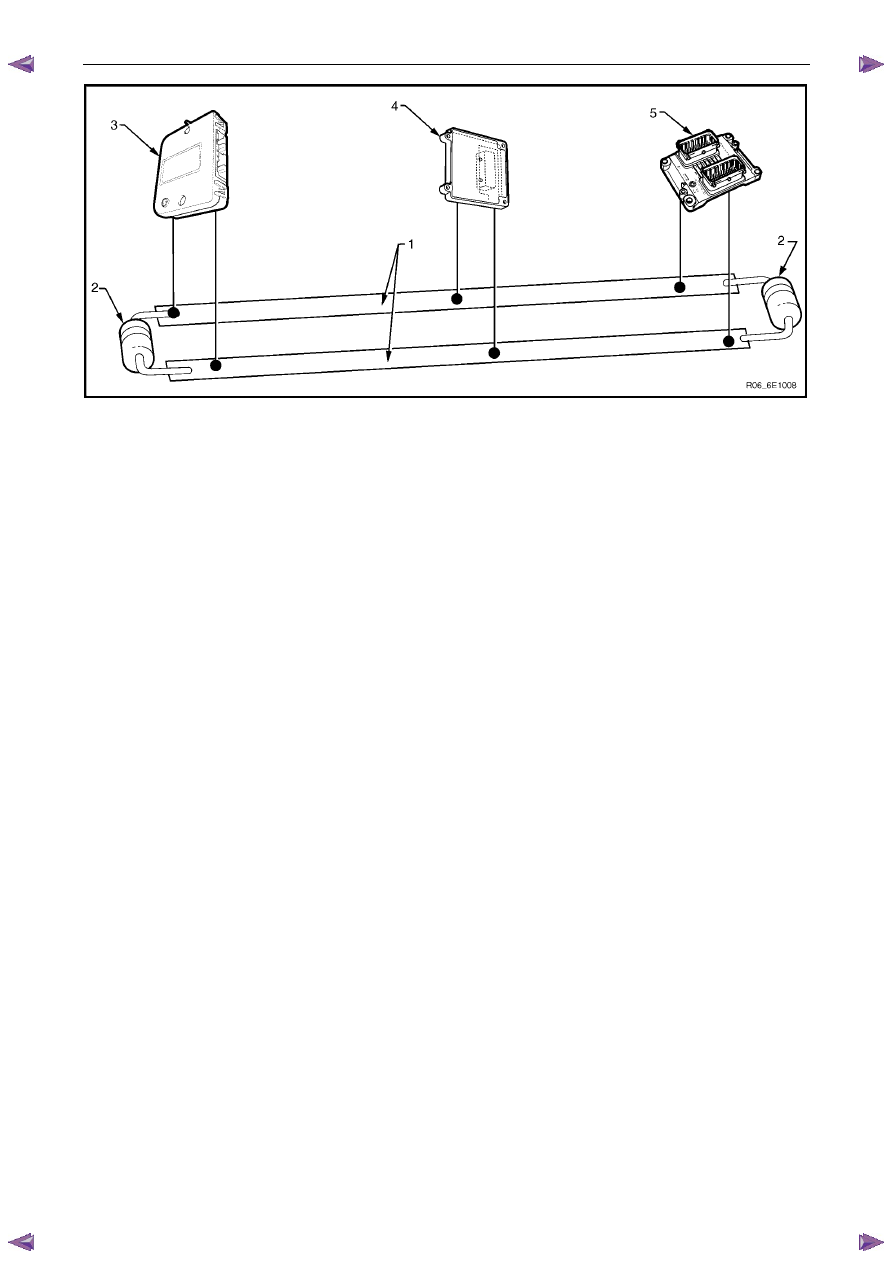
Figure 6E1 – 1
Legend
1
CAN Bus Lines
2
Cut-off Resistors (resistors are integrated into the PIM and
ECM)
3
Powertrain Interface Module (PIM)
4
Transmission Control Module (TCM)
5
Engine Control Module (ECM)
Serial Data
When information is sent from one control module to another via the serial data bus, the information sent is known as
serial data. Serial data in its electronic form, is made up of rapidly changing high to low voltage pulses strung together.
Each string of voltage pulses represents a message.
•
GM LAN serial data has two data lines along which serial data is sent. These lines are known as CAN_HI and
CAN_LO.
•
CAN HI – The CAN HI data line is a 3.6 V data line that toggles the voltage between 2.5 V and 3.6 V
(referenced to ground). When there is no communication on the CAN HI data line, the system voltage
is 2.5 V.
•
CAN LO – The CAN LO data line is a 2.5 V data line that toggles the voltage between 2.5 V and 1.4 V
(referenced to ground). When there is no communication on the CAN LO data line, the system voltage
is 2.5 V.
Serial Data Communication Protocols
General Motors Local Area Network (GM LAN)
GM LAN is a communication protocol based on the Controller Area Network physical layer. The main difference between
GM LAN and CAN is the way in which the messages are structured.