Isuzu KB P190. Manual - part 909


  Index      Isuzu     Isuzu KB P190 - service repair manual 2007 year


Search            


Content   ..  907  908  909  910   ..


Isuzu KB P190. Manual - part 909


Starting System – V6 

Page 6D1-2–28 


10 

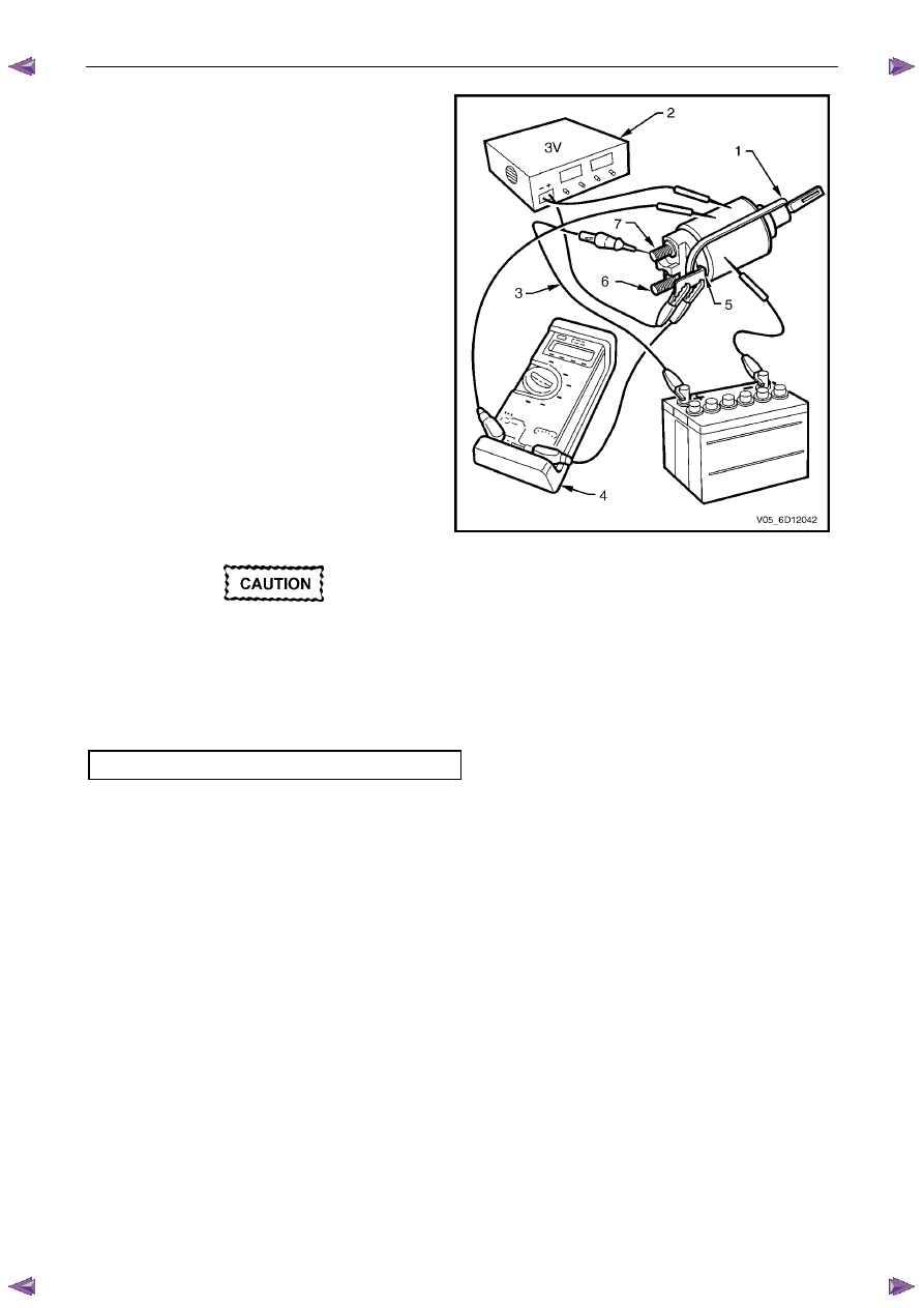
Fit a rubber band (1) around the plunger and 
switch housing to avoid ejecting the plunger. 

11 

Hold the solenoid switch vertically with the 
plunger pointing upwards. 

12 

Use a power supply (2) capable of supplying 30 A 
or use a battery and a variable resistor. 

13 

Set the power supply to 3.0 V. 

14 

Connect the power supply negative lead to the 
solenoid switch body. 

15 

Connect the power supply positive lead to the 
solenoid switch terminal P – 3 (5). 

16 

Connect a test lamp (3) between the solenoid 
switch terminal P – 4 (7) and the battery. 

17 

Connect a multimeter set to measure voltage (4) 
between the solenoid switch terminal P – 3 (5) 
and the solenoid switch housing. 

18 

Press the solenoid plunger in until the test lamp 
illuminates. 

19 

Allow the plunger to move out by 8 – 10 mm. 

20 

Hold the plunger in this position. 


The test duration for the following step 
should be no more than 2 seconds. 


Figure 6D1-2 –  25 

21 

Slowly increase the power supply voltage on the solenoid switch terminal P – 3 until the plunger pulls in. 

22 

Record the multimeter reading and reduce the voltage applied to the solenoid switch terminal P – 3. 

23 

Replace the solenoid switch if the voltage reading is significantly higher than the specification. 

Pull-in voltage @ 20

°C............................................8.0 V 

24 

Check the continuity across the main contacts in the switch. 

25 

Increase the voltage on the solenoid switch terminal P – 3 (5) until the plunger pulls in. 

26 

Ensure the test lamp illuminates fully. 


Starting System – V6 

Page 6D1-2–29 


27 

Replace the solenoid switch if the test lamp 
illuminates poorly. 

28 

Set the power supply to 12 V (1). 

29 

Connect the power supply positive lead to the 
solenoid switch terminal P – 3 (2). 

30 

Connect the power supply negative lead to the 
solenoid switch housing (3). 

31 

Press the plunger in fully. 

32 

Release the plunger. The hold-in winding should 
hold the plunger in. 

33 

Replace the solenoid switch if the winding does 
not hold the plunger in. 

34 

Decrease the voltage until the plunger releases.

35 

Record the multimeter reading. 

36 

Replace the solenoid switch if the voltage 
reading is significantly higher than the 
specification. 

Hold-in voltage @ 20

°C..........................1.7 – 3.0 V 

37 

Connect a test lamp between the solenoid 
switch terminal P – 4 and the 12 volt power 
supply. 

38 

Press the plunger in until the test lamp 
illuminates. 

39 

Attempt to press the plunger into the solenoid 
switch housing a further 1 mm. 

40 

Replace the solenoid switch if the plunger 
cannot move at least a further 1 mm. 


Figure 6D1-2 –  26 

41 

Connect the positive lead of a 24 volt power 
supply (1) to the positive lead of a multimeter set 
to measure voltage. 

42 

Connect the negative lead of a 24 volt power 
supply to the solenoid switch housing (2). 

43 

Connect the multimeter negative lead to the 
solenoid switch terminal P – 4 (3). 

44 

Press the plunger (4) in fully. 

45 

Release the plunger. The plunger should return 
to its rest position. 

46 

Replace the solenoid switch if the plunger does 
not return.  

N O T E  

This indicates the windings have an 
internal winding short circuit. When the 
solenoid switch is connected in this way, 
the winding fields are in opposition to each 
other. 


Figure 6D1-2 –  27 


Starting System – V6 

Page 6D1-2–30 


5 Specifications 

Type............................................... Six Pole Permanent Magnet, Four Brush, Planetary Drive 

Rotation (Drive-End View) ....................................................................................... Clockwise 

Number of Pinion Teeth........................................................................................................10 

N o   l o a d :  

Minimum RPM ..................................................................................................................2370 

Maximum Current Draw............................................................................ 65 A at 12.0 

± 0.1 V 

M Terminal Voltage..................................................................................................... 12 

± 1 V 

L o c k e d :  

Maximum Current (Including Solenoid Switch) ............................................................... 780 A 

M Terminal Voltage............................................................................................................. 4 V 

Minimum Torque............................................................................................................ 20 Nm 

S o l e n o i d   d e t a c h e d :  

Pull-in Winding Resistance @ 20°C ................................................................... 0.33 – 0.37 

Ω 

Hold-in Winding Resistance @ 20°C .................................................................. 0.75 – 0.87 

Ω 

Pull-in Voltage @ 20°C ..........................................................................................8 V @ 20

°C 

Hold-in Voltage @ 20°C.......................................................................................... 1.7 – 3.0 V 

Starting System – V6 

Page 6D1-2–31 


Torque Wrench Specifications 

..................................................................................................................... Nm 

Solenoid Switch Mounting Screw ........................................................ 4.1 – 7.6 

Solenoid Switch Terminal M Nut ................................................................ 10.0 

Solenoid Switch Terminal P – 3 Nut ........................................................... 10.0 

Starter Motor Mounting Bolt........................................................................ 45.0 

Knock Sensor Bolt ................................................................................ 23.0 Nm 

Starter Motor Heat Shield Lower Bolt ................................................... 23.0 Nm 

Starter Motor Heat Shield Upper Screw ........................................ 3.0 – 5.0 Nm 


Content   ..  907  908  909  910   ..