Isuzu KB P190. Manual - part 882
Engine Management – V6 – Service Operations
Page 6C1-3–4
1 General
Information
1.1 General
Description
This Section describes the correct service procedures to repair and test components of the V6 engine management
system. Emphasis is placed on the proper procedures and repair of components related to this specific system.
For component description, operation and location, refer to 6C1-1 Engine Management – V6 – General Information.
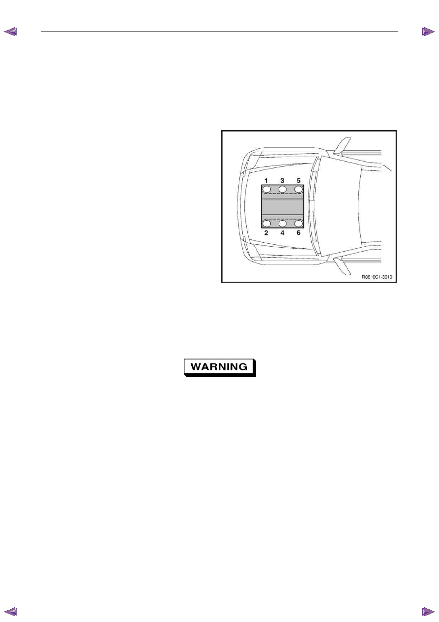
Engine cylinder identification follows the international
standard OBD II. This standard calls for the engine cylinder
bank number one to be identified by the location of cylinder
number one. Therefore the numbering for the V6 engine is:
•
1, 3, 5 – Right-hand side (Bank 1).
•
2, 4, 6 – Left-hand side (Bank 2).
The engine firing order is 1, 2, 3, 4, 5, 6.
Figure 6C1-3 – 1
1.2
Service Precautions and Requirements
Service Precautions
The following safety and precautionary
directions must be followed when servicing
the engine management system otherwise
personal injury and / or improper system
operation may occur:
•
If working on a vehicle which has been subjected to an under bonnet thermal incident (fire), wear appropriate
protective clothing to prevent personal injury. Components that contain fluoro-elastomer may produce a corrosive
bi-product when subjected to extreme heat.
•
Disconnection of the battery affects certain vehicle electronic systems. Refer to the battery disconnection
procedure in 6D1-3 Battery – V6 before disconnecting the battery.
•
Disconnect the battery negative lead when performing the following procedures:
•
disconnecting the engine control module (ECM) connectors, or
•
charging the battery.
•
Disconnect the battery negative lead and the ECM connectors before attempting any electric welding on the vehicle.
•
Do not start the engine if the battery terminal is not properly secured to the battery.
•
Do not disconnect or reconnect the following while the ignition is switched on or when the engine is running:
•
any engine management system component wiring connector, or
•
battery terminal leads.