Isuzu KB P190. Manual - part 825


  Index      Isuzu     Isuzu KB P190 - service repair manual 2007 year


Search            


Content   ..  823  824  825  826   ..


Isuzu KB P190. Manual - part 825


Engine Management – V6 – Diagnostics 

Page 6C1-2–22 


5 Symptoms 

Diagnostics 

5.1 

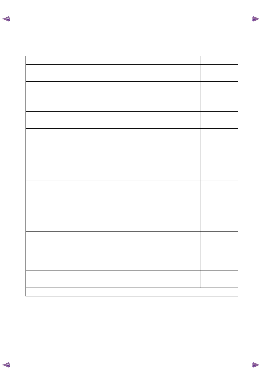
Symptoms Diagnosis Table 

Step Action 

Yes 

No 

Has the Diagnostic System Check been performed? 

Go to Step 2 

Refer to 

4.4 Diagnostic 

System Check 

Is the fault intermittent? 

Refer to 

5.2 Intermittent 

Fault Conditions 

Go to Step 3 

Does the engine backfire? 

Refer to 

5.3 Backfire 

Go to Step 4 

Does the engine crank but does not run? 

Refer to 

5.4 Cranks 

But 

Does Not Run 

Go to Step 5 

Does the engine cut-out or miss? 

Refer to 

5.5 Cuts 

Out, 

Misses 

Go to Step 6 

Is there a detonation or spark knock noise coming from the engine? 

Refer to  

5.6 Detonation / 

Spark Knock 

Go to Step 7 

Is there an engine dieseling or run-on condition? 

Refer to 

5.7 Dieseling, 

Run-on 

Go to Step 8 

Is there an engine hard starting condition? 

Refer to 

5.8 Hard 

Start 

Go to Step 9 

Is there an engine hesitation, sag or stumble condition? 

Refer to 

5.9 Hesitation, 

Sag and Stumble 

Go to Step 10 

10  Does the engine suffer from lack of power, sluggishness or 

sponginess? 

Refer to 

5.10 Lack of Power, 

Sluggishness or 

Sponginess 

Go to Step 11 

11  Does the engine suffer from poor fuel economy? 

Refer to 

5.11 Poor 

Fuel 

Economy 

Go to Step 12 

12  Does the engine suffer from rough, unstable or incorrect idle and 

engine stalling? 

Refer to 

5.12 Rough, 

Unstable, Incorrect 

Idle or Stalling 

Go to Step 13 

13  Does the engine surge or chuggle? 

Refer to 

5.13 Surges 

Chuggles 

Go to Step 14 

When all diagnosis and repairs are completed, check the system for correct operation. 

5.2 

Intermittent Fault Conditions 

Description 

A fault condition is intermittent if one of the following conditions exists: 

• 

the fault condition is not always present, 

• 

the fault condition cannot be presently duplicated, or 

Engine Management – V6 – Diagnostics 

Page 6C1-2–23 


• 

there is no Current DTC but a History DTC is stored. 

Diagnostic Table  

Checks Actions 

Preliminary 

• 

Perform the preliminary checks. Refer to 4.3 

Preliminary Checks in this 

Section. 

• 

Gather information from the customer regarding the conditions that trigger the 
intermittent fault such as: 

• 

At what engine or ambient temperature range does the fault occur? 

• 

Does the fault occur when operating aftermarket electrical equipment inside 
the vehicle? 

• 

Does the fault occur on rough roads or in wet road conditions? 

• 

If the intermittent fault is a start and then stall condition, check the immobiliser 
system. Refer to 11A Immobiliser. 

Tech 2 Tests 

The following are lists of Tech 2 diagnostic tests that may be used to diagnose 
intermittent faults: 

• 

Wriggle test the suspected wiring harness and connectors while observing Tech 2 
operating parameters. If Tech 2 read-out fluctuates during this procedure, check 
the tested wiring harness circuit for a loose connection. 

• 

Observe the freeze frame / failure records for the suspected history DTC and then 
operate the vehicle in the conditions that triggers the intermittent fault while an 
assistant observes the suspected Tech 2 operating parameter data. 

• 

Capture and store data in the snapshot mode when the fault occurs. The stored 
data may be played back at a slower rate to aid diagnostics. Refer to Tech 2 User 
Instructions for further information on the Snapshot function. 

• 

Compare the engine operating parameters of the engine being diagnosed to the 
engine operating parameters of a known good engine. 

Malfunction Indicator Lamp 

The following conditions may cause an intermittent Malfunction Indicator Lamp fault 
with no DTC listed: 

• 

Electromagnetic interference (EMI) caused by a faulty relay, ECM controlled 
solenoid, switch or other external source. 

• 

Incorrect installation of aftermarket electrical equipment such as the following: 

• 

mobile phones, 

• 

lights, or 

• 

radio equipment. 

• 

ECM grounds are loose. 

Engine Management – V6 – Diagnostics 

Page 6C1-2–24 


Checks Actions 

Temperature Related 

Temperature related intermittent fault condition occurs only when the engine or ambient 
temperature is hot, or only when it is cold. 

• 

If the intermittent fault is heat related, review Tech 2 data in relationship to the 
following:  

• 

high ambient temperature, 

• 

engine generated heat, 

• 

circuit generated heat due to a poor electrical connection or high electrical 
load, and 

• 

higher than normal load conditions (towing, etc.). 

• 

If the intermittent fault is related to cold ambient or engine temperature, review 
Tech 2 data in relationship to the following: 

• 

low ambient temperature, and 

• 

the fault condition that occurs only on a cold start situation. 

Additional Tests 

• 

Incorrect installation of aftermarket electrical equipment such as the following: 

• 

mobile phones, 

• 

theft deterrent alarms, 

• 

lights, or 

• 

radio equipment. 

• 

Electromagnetic interference (EMI) caused by a faulty relay, ECM controlled 
solenoid or switch. The fault is triggered when the relay or solenoid is activated. 

• 

Test the A/C compressor clutch and some relays that contain a clamping diode or 
resistor for an open circuit. 

• 

Test the generator for a faulty rectifier bridge that may allow the A/C noise into the 
ECM electrical circuit. 

When all diagnosis and repairs are completed, check the system for correct operation. 

5.3 Backfire 

Description 

The air / fuel mixture in the intake manifold or in the exhaust system ignites which produces a loud popping noise. 

Checks Actions 

Preliminary 

Perform the Preliminary Checks. Refer to 4.3 

Preliminary Checks in this 

Section. 

Sensor / System 

• 

Check the air intake system and crankcase for air leaks. 

• 

Check the PCV System for correct operation. Refer to 6A1 Engine Mechanical – 
V6. 

• 

Use Tech 2 to monitor the knock sensor system for excessive spark retard 
activity. Check for items that cause spark retard activity. 

Engine Management – V6 – Diagnostics 

Page 6C1-2–25 


Checks Actions 

Fuel System 

• 

Check the fuel system for the following fault conditions. Refer to 6C Fuel System 
– V6 – V6. 

• 

restricted fuel filter, 

• 

incorrect fuel pressure, and 

• 

contaminated fuel. 

• 

Check the operation of the fuel injectors. Refer to 6C1-3 Engine Management – 
V6 – Service Operations. 

• 

Perform the fuel injector balance test, refer to 6.3 

Fuel Injector Balance 

Test in this Section. 

• 

Check the items that can cause an engine to run lean. 

• 

Check the items that cause an engine to run rich. 

Ignition System 

• 

Check for an intermittent ignition circuit malfunction.  

• 

Inspect for moisture or corrosion around the spark plug / ignition coil area. 

• 

Test the ignition coil voltage output. Refer to 6C1-3 Engine Management – V6 – 
Service Operations. 

• 

Remove and inspect the spark plugs. Refer to 6C1-3 Engine Management – V6 – 
Service Operations. 

N O T E  

If the spark plugs are fouled, determine the cause of the fouling before 
replacing the spark plugs. Refer to 6C1-3 Engine Management – V6 – 
Service Operations. 

• 

Check for loose ignition coil ground circuit. 

Engine Cooling System 

Check the engine for over-heating. Refer to 6B1 Engine Cooling – V6. 

Engine Mechanical 

Check for the following engine fault conditions. Refer to 6A1 Engine Mechanical – V6. 

• 

low compression, and 

• 

worn valve train components. 

Additional Checks 

• 

Check the exhaust system for possible restrictions. Refer to 6F Exhaust System – 
V6. 

• 

Electromagnetic interference (EMI) on the crankshaft position (CKP) sensor can 
cause an engine misfire condition.  


Using Tech 2, monitor the engine speed parameter. A sudden increase in the 
engine speed parameters without moving the throttle position indicates that an 
Electromagnetic Interference fault may be present.  


Wiring harness routing which may be positioned very close to a high voltage or 
high current device such as the following may induce EMI: 

• 

secondary ignition components, or 

• 

motors and generators. 


Dirty starter motor commutator or brushes can mask the crankshaft position 
sensor signal. 

• 

Check the torque converter clutch (TCC) operation. A TCC that applies too soon 
can cause engine detonation, which will trigger spark retard activity. Refer to 7C1 
Automatic Transmission – 4L60E – General Information. 

When all diagnosis and repairs are completed, check the system for correct operation. 


Content   ..  823  824  825  826   ..