Isuzu KB P190. Manual - part 809
Fuel System – V6
Page 6C – 34
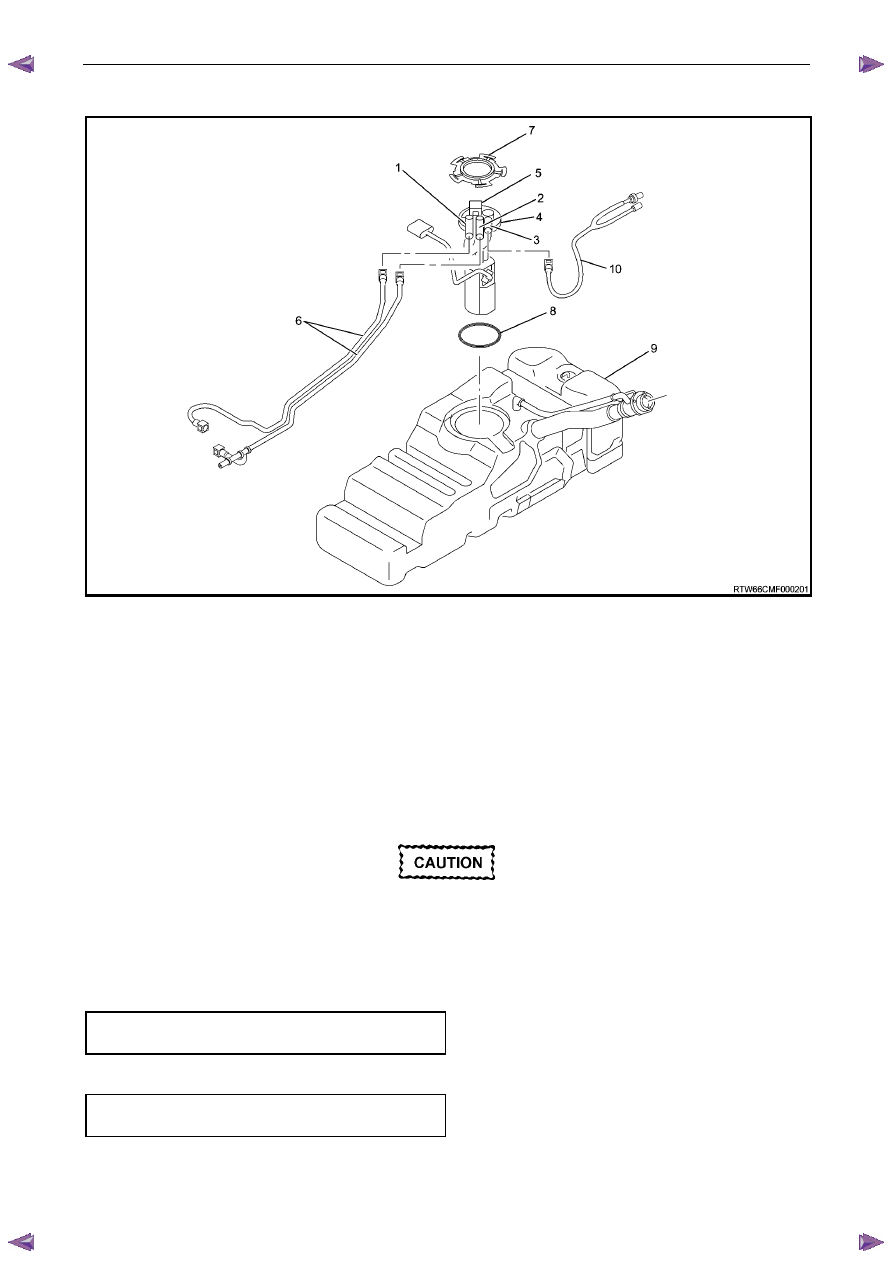
Fuel Tank Lines
Figure 6C – 38
Legend
1
Fuel Feed Line
2
Fuel Return Line
3
Fuel Vapour emission port
4
Fuel Pump and Sender Assembly
5
Connector; Fuel Pump and Sender
6 Fuel
Lines
7
Retainer Ring (Fuel Pump Lock)
8
“O” Ring Seal
9
Fuel Tank Assembly
10
Fuel Vapour Vent Line
Reinstall
Ensure the plastic fuel line clips are in good
condition before proceeding. If not, replace
the defective clips.
Reinstallation of the stone guard and fuel lines is the reverse of the removal procedure, noting the following:
1
Tighten the Fuel line securing nut to the correct torque specification, refer to Figure 6C – 39.
Fuel line securing nut
torque specification .........................................8 – 12 Nm
2
Tighten the stone guard securing bolts to the correct torque specification.
Stone guard securing bolt
torque specification .....................................5.0 – 7.0 Nm